background image

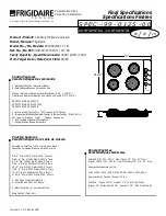
3.3 HOTPLATES - TO REMOVE
a) Remove facia panel as detailed in Section 3.1 and

raise hotplate assembly as detailed in Section 3.2.

b) Remove hotplate connections and undo central

fixing nut. This will allow hotplate to be removed

from top.

Fit replacement plate in reverse order, referring to

wiring diagram when re-connecting.

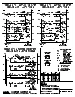
3.4 CONTROL SWITCHES - TO REMOVE
a) Remove control panel as detailed in Section 3.1.
b)Remove switch connections, note cable

arrangement.

c) Pull off control knob and undo fixing screws to

release switch. Fit new switch in reverse order,

ensure that earth bonding wire is attached to it.

3.5 PILOT LAMPS - TO REMOVE
a) Remove control panel as detailed in Section 3.1.
b) Pull off connections to lamp.
c) Remove nut at panel rear to release lamp. Fit

replacement in reverse order.

3.6 OVEN ELEMENTS - TO REMOVE
a) Remove control panel as detailed in Section 3.1.
b) Remove outer side panels as follows. Undo

screws in rear flange of panel. Swing panel rear

outward slightly then forward to release front fixing.

c) Open door and remove base panel.
d) Remove element connections and undo fixing nut.
e) Withdraw element from inside oven. Replace

element in reverse order, ensuring small earth

bonding wire connection is securely fastened in

place.

Summary of Contents for E350/30

Page 1: ...nstration of the operation and cleaning of the appliance IT IS MOST IMPORTANT THAT THESE INSTRUCTIONS BE CONSULTED BEFORE INSTALLING AND COMMISSIONING THIS APPLIANCE FAILURE TO COMPLY WITH THE SPECIFIED PROCEDURES MAY RESULT IN DAMAGE OR THE NEED FOR A SERVICE CALL PREVENTATIVE MAINTENANCE CONTRACT In order to obtain maximum performance from this unit we would recommend that a maintenance contract...

Page 2: ... Gas water and electrical supply external to unit Light bulbs Re installing vacuum in kettle jackets Replacement of grill burner ceramics when damage has been clearly caused by misuse Where an engineer finds no fault with a product that has been reported faulty Re setting or adjustment of thermostats when unit is operating to specification Cleaning and unblocking of fryer filter systems due to cus...

Page 3: ... links supplied and connect to the mains strictly in accordance with Figure 1 N L1 L2 L3 Supply Cables N L1 d Switch appliance on Ensure that all controls elements and pilot lamps function correctly e After completion of installation demonstrate method of operation to kitchen staff Point out location of mains isolating switch to be shut down in event of an emergency or during cleaning SECTION 3 SE...

Page 4: ...h Fit new switch in reverse order ensure that earth bonding wire is attached to it 3 5 PILOT LAMPS TO REMOVE a Remove control panel as detailed in Section 3 1 b Pull off connections to lamp c Remove nut at panel rear to release lamp Fit replacement in reverse order 3 6 OVEN ELEMENTS TO REMOVE a Remove control panel as detailed in Section 3 1 b Remove outer side panels as follows Undo screws in rea...

Page 5: ...4 3 1 2 5 P 2 P 1 P 3 4 3 1 2 5 P 2 P 1 P 3 4 3 1 2 5 P 2 P 1 P 3 4 3 1 2 5 P 2 P 1 P 3 E 3 5 0 3 0 R A N G E W I R I N G D I A G R A M ...

Reviews: