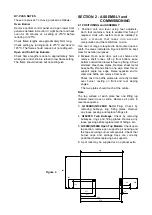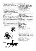
Thermocouple
Burner
(unscrew to
remove)
Burner jet
Pilot injector
15mm +/-1mm
g) Replace all parts in reverse order. Check gas joints
for gas tightness. Adjust by-pass screw to achieve
a flame cone height of approx. 5mm. Check flame
stability by turning control knob between high and
low flame operation.
3.4.3 Oven Thermocouple
a) Remove vertical control panel and RH outer panel
as described in Sections 3.2.3 and 3.2.1.
b) Undo thermocouple nut at FFD rear after partially
removing control.
c) Open bottomfront panel and disconnect nut which
secures thermocouple head to pilot assembly and
withdraw.
d) Fit new thermocouple. Ensure the head is pushed
firmly into position before tightening nut and that
the FFD nut is not overtightened.
A quarter turn past hand tight must only be
employed to prevent fracture of this electrical joint.
e) Replace panels in reverse order.
3.4.4 Solid Top Flame Failure Device/Gas Cock
a) Remove control panel. See Section 3.2.4.
b) Remove solid top hob fillings.
c) Undo both large compression nuts on inlet and
outlet pipes.
d) Disconnect thermocouple nut.
e) Undo pilot supply pipe on ignition flame supply
pipe.
f) Undo fixings that secure control fixing plate to
bracket.
g) Remove fixing plate from old control and secure it
to replacement.
h) Replace all parts in reverse order.
3.4.5 Solid Top Thermocouple
(G1006BX/G1026BX)
a) Remove bullseye rings and hob fillings.
b) Undo thermocouple to FFD nut.
c) Undo locknuts which secure thermocouple to
bracket. Withdraw thermocouple.
d) Replace in reverse order. Position thermocouple
tip, 38mm above base as shown in Figure 7.
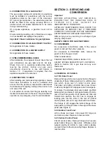
Figure 7
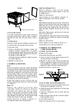
3.4.6 Twin Bullseye (Thermocouple Replacement)
a) Remove bullseye rings and hob castings.
b) Remove burner centre support.
c) Remove burner controls cover panel.
d) Remove control panel as detailed in Section 3.2.4.
e) Remove burner closest to thermocouple for clear
access to thermocouple nut.
f) Undo thermocouple nut at gas control tap.
g) Remove thermocouple.
h) Replace in reverse order.
Figure 8
3.5 OVEN PIEZO UNIT REMOVAL
a) Open bottomfront panel.
b) Remove fixings that secure piezo unit bracket to
base plate. Partly withdraw piezo unit and pull
igniter lead off.
c) Remove existing piezo unit from fixing bracket and
fit replacement.
d) Attach igniter lead to replacement piezo before
positioning.
e) Replace panel in reverse order.
3.6 REMOVAL OF OVEN SPARK ELECTRODE
a) Open bottomfront panel.
b) Remove thermocouple. See Section 3.4.3.
c) Undo nut that secures electrode lead.
d) Undo gland nut and withdraw electrode.
e) Replace in reverse order and ensure thermocouple
head is correctly positioned as detailed in Section
3.4.3. The electrode conductor terminal should be
clear of any adjacent metal parts.
3.7 THERMOSTAT
3.7.1 Oven Control Thermostat
a) Remove vertical control panel and RH outer panel.
(see Sections 3.2.3 and 3.2.1.)
b) Undo inlet and outlet pipes compression nuts.
c) Remove fixings that secure right-angled bracket to
Z bracket.
d) Open oven door and release phial by removing
clips which secure it to roof baffle.
e) Gently pull phial and capillary tube through oven
side hole and withdraw thermostat.

