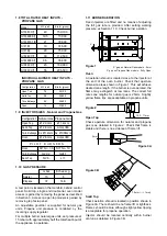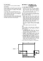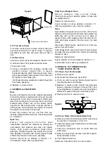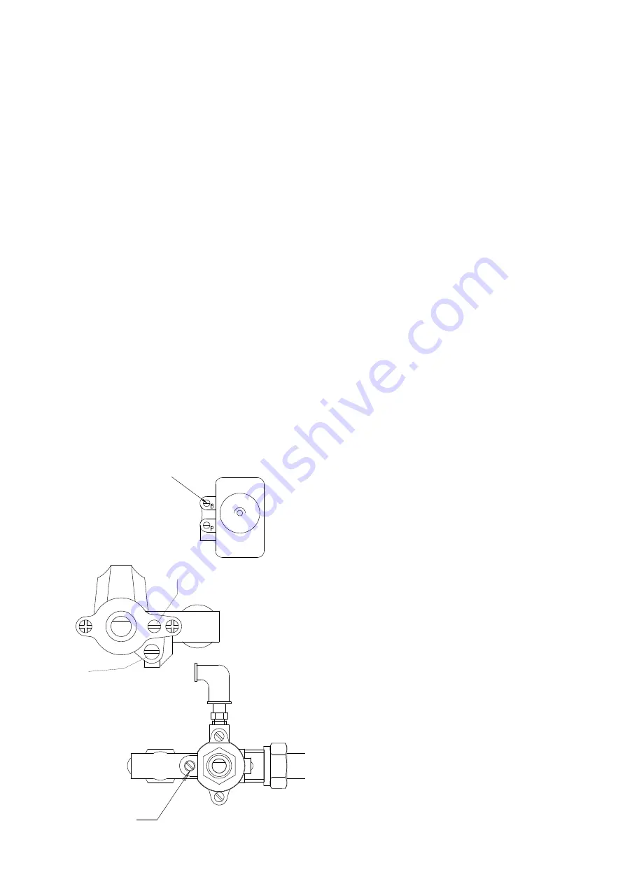
Oven thermostat bypass screw
Pilot
(Solid Top Only)
Bypass screw
Low flame
adjustment
f) Remove right-angled bracket from existing
thermostat and fit it to replacement.
g) Replace all parts in reverse order and check gas
joints for tightness.
3.7.2 To Check and Adjust the Thermostat
a) Remove control panel as detailed in Section 3.2.3.
b) Replace knob and turn to 200
o
C position. This
should be the temperature at this setting.
c) Place a temperature measuring device at
geometric centre of oven and light oven.
d) Allow oven to heat up for 30 minutes. Observe
temperature is steady. Compare value obtained
with required value of 200
o
C.
Example - Oven at 190
o
C.
Action
Turn knob to a higher setting until a temperature of
200
o
C+/-5
o
C is obtained. Pull knob off without
rotating spindle. Undo fixings on adjusting flange at
spindle base. Replace knob and turn it back to 200
o
C
setting. Remove knob and tighten adjusting flange
fixings. Check temperature remains steady at new
setting for 200
o
C.
Reverse action if oven temperature is above or below
200
o
C.
e) Turn thermostat to lowest setting and adjust
by-pass screw to achieve flame cone length of
approximately 5mm. Check flame stability as
detailed in Section 1.11.
Figure 9
3.8 GAS TAPS and FFD
3.8.1 Replacement Taps for Open Top and
Solid Top Burners (G1006BX/G1026BX)
a) Remove control panel as detailed in Section 3.2.4.
b) Remove hob lift-off components.
c) Undo inlet/outlet pipe compression nuts.
d) Disconnect thermocouple nut.
For solid top units, proceed with e) to g).
e) Undo pilot supply pipe.
f) Undo fixings that secure control location plate to
bracket.
g) Remove fixing plate from previous control and
secure to replacement.
Replace parts in reverse order.
Also check FFD thermocouple position at low flame
operation. Check open top flame stability on low
flame settings by turning control between high and
low settings.
To set by-pass rate: Aimfor flame cone lengths of
approximately 5mm. Typically, this may be achieved
by withdrawing by-pass screw fromits closed position
by:
Open Top
Natural Gas - Half turn
Propane Gas - Quarter turn
Solid Top
Propane Gas - Two Turns
3.8.2 Twin Bullseye
a) Remove bullseye rings and hob castings.
b) Remove centre support.
c) Remove burner control panel.
d) Remove control panel as detailed in Section 3.2.4.
e) Undo saddle clamp plate to float rail.
f) Unscrew burner assembly and manifold bracket
fromside panel and crown plate.
g) Remove burner assembly c/w with gas tap and
manifold bracket to gain complete access to
pipework.
h) Remove pilot pipe, main feed pipe and
thermocouple nut from tap.
j) Remove pilot pipe adaptor from gas tap.
k) Replace components in reverse order.
m) Replace all parts in reverse order.

