To Extinguish The Burner
Turn the tap fullyclockwise to the OFF position.
LH Knob
RH Knob
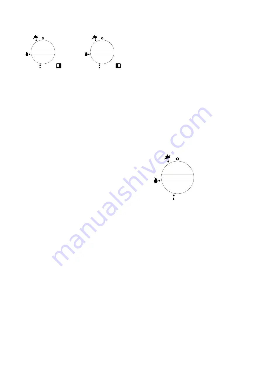
Figure 3
2.2 SOLID HOTPLATE
The single solid hotplate is composed of two filling
plates, one rings and one centre bullseye. A radial
burner is located centrallybelow the hotplate. This is
operated bythe related control knob. See Figure 3 to
identifytap markings.
The two hotplate version has four filling plates, two
rings and two centre bullseyes. A radial burner is
located centrallybelow each hotplate and is operated
bythe related control knob. See Figure 3 to identify
tap markings.
Warning
If the burner is extinguished intentionallyor
otherwise, NO attempt to re-light the gas should be
made until at least 3 minutes have elapsed.
The procedure for lighting a burner, is as follows
(Refer to Figure 3) -
1. Remove the centre bullseye using the special tool
provided.
2. Have a lit taper or match readyin one hand.
3. With the other hand, push the control knob in and
turn it anti-clockwise until the knob mark is aligned
with the ignition symbol.
4. Applythe taper or match to the pilot, keep the knob
pushed in.
5. Release the knob after approximately20 seconds.
The pilot should remain alight. If not, push in the
control knob and turn it clockwise to the off
position. Wait 3 minutes, then repeat form Step 2.
6. Having established the pilot flame, replace the
centre bullseye.
7. Turn knob anti-clockwise to the full flame symbol.
8. If desired, the burner can be turned down to the
low or simmer setting byturning the knob fully
anti-clockwise to the low flame symbol.
To Turn the Burner OFF
9. To turn a burner down but leaving it lit, turn the
knob to the ignition symbol.
10. To extinguish a burner, push the knob in and turn
to the off position.
Note
Most turning movements of the knob have to be
preceded bypushing it in.
Using the Solid Hotplate
Getting the best out of this type of heat source is
largelya matter of experience coupled with the
requirements of the task in hand. For certain
applications such as heating a pot quickly, it is
expedient to remove the centre ring and place the pot
directlyover the burner. If it is necessaryto heat the
entire surface, the ring must be in position.
In the interests of economy, it is recommended that
the unit should not be left unattended on full setting.
If it is necessaryto keep the hob area hot for any
length of time, the control should be set to low.
Never leave the gas on without a pot when the centre
ring has been removed as such practice wastes
energy. The hottest area of the plate is the centre of
the bullseye and toward the rear. The front and sides
are cooler.
2.4 SOLID HOTPLATE
The single solid hotplate is composed of two filling
plates, a ring and a centre bullseyes. The burner is
located directlybelow the centre ring and is operated
bythe related control knobs. See Figure 4 to identify
the tap icons.
Figure 4
Warning
Should the burner become extinguished intentionally
or otherwise, NO attempt to relight it should be made
until at least 3 minutes have elapsed.
The procedure for lighting a burner, is as follows
(Refer to Figure 4) -
1. Remove the centre bullseye using the special tool
provided.
2. Have a lit taper or match readyin one hand.
3. With the other hand, push in the control knob and
turn it anti-clockwise till the knob mark is opposite
the ignition symbol.
4. Applythe taper or match to the pilot while keeping
the knob pushed in.
5. Release the knob after approximately20 seconds.
The pilot should remain alight. If not, push the
knob in and turn it clockwise to the off position.
Wait 3 minutes, then repeat form Step 2.
6. Having established the pilot flame, replace the
centre bullseye.
7. Turn the knob anti-clockwise to the full flame
symbol.
8. If desired, the burner can be turned down to the
low or simmer setting byturning the knob fully
anti-clockwise to the low flame symbol.


