1
0
3.7 BURNER RESET SWITCH
a)
Remove drain handle and front panel fixings.
b)
Remove electrical connections and remove switch by squeezing side fixings to push it through aperture.
c)
Replace part in reverse order.
3.8 CONTROL BOARD (small)
a)
Remove bolts from top and bottom of control panel.
b)
Pull control panel forward then drop down.
c)
Disconnect electrics and remove fixings enabling controller to be removed.
Replace part in reverse order.
3.9 IGNITER/SENSOR
a)
Remove side panels and undo connection wires from ignition control box.
b)
Undo electrode/igniter nuts from underside of burner.
c)
Pull igniter and gasket out of location.
d)
Fit new gasket to igniter and replace parts in reverse order. Ensure that a good earth connection is made.
Note: This can be achieved by removing LH side panel only and/or access plate. Refer to Section 2,
Figure 4.
3.10 DRAIN VALVE
a)
Ensure fry pot is empty. Refer to Section 8.
b)
Remove nut from handle and lift handle off.
c)
Remove front panel fasteners.
d)
Disconnect wiring, noting all connections.
e)
Remove front panel to access drain valve.
f)
Undo drain pipe and using appropriate size of spanner, remove drain valve.
g)
Replace in reverse order and check for oil leak.
3.11 FILTRATION PUMP (
When Fitted
)
a)
Remove back panel and remove flexi-hose at filtration pump.
b)
Disconnect electrical coupling plug.
c)
Undo bolts from below base panel that secure pump bracket to base and lift clear.
d)
Disconnect pump from bracket and replace in reverse order.
Note: Check for oil leaks before replacing any panels.
3.12
FILTRATION PUMP PIPEWORK
a)
Remove back panel and flue bolts from rear.
b)
Undo quick release connection from top of outer flue.
c)
Remove flexi-hose at filtration pump.
d)
Lift entire flue assembly clear.
e)
Replace in reverse order.
f)
Check for oil leaks before replacing any panels.
3.13
FAN SPEED BOARD (larger board)
a)
Open control panel as detailed in Section 3.8.
b)
Undo electrical connections and pull ignition board gently from fasteners. Carefully replace board in reverse
order.
3.14
IGNITION CONTROL BOX
a)
Remove LH side panel at rear of side enclosure.
b)
Remove fixing from control box lid.
c)
Slide control box from pins on valve and pull clear of case.
d)
Undo electrical connections.
e)
Replace in reverse order & test.
Note: Control is in
“lock-out”
when new.
Summary of Contents for G2844F
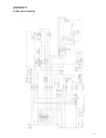
Page 25: ...25 SECTION 11 G2844F CIRCUIT DIAGRAM...
Page 26: ...G2845F CIRCUIT DIAGRAM...
Page 27: ...27 G2844F WIRING DIAGRAM...
Page 28: ...G2845F WIRING DIAGRAM...


