NATURAL GAS
MAIN
PILOT
PROPANE GAS
MAIN
PILOT
ù1.07
-
ù1.75
-
Open Top
ù1.4
SIT
19
ù 2.4
SIT
36
Solid Top
AMAL
170
-
ù 1.8
-
Oven
mbar
inches w.g.
6
14.8
15
37
NATURAL
PROPANE
1.8 INJECTOR SIZES -
NATURAL andPROPANE GAS
Dimensions in mm
1.9 GAS PRESSURE
The pressure test point is located on thermostat
situated behind front facia panel.
An adjustable governor (Rc
1
/
2
) is provided on natural
gas units.
Do not use a governor on propane units.
1.10 BURNER ADJUSTMENT -
NATURAL andPROPANE GAS
1.10.1 Open Top
The burners are fitted with fixed injectors and aeration
settings. No adjustment is necessary.
Open Top Bypass Rate
Minimum gas flow to burner is governed by the size of
fixed drilled hole in gas tapby-pass screw. The orifice
size in screw is ù0.84mm for NATURAL Gas and
ù0.5mm for PROPANE.
1.10.2 SolidTop
The burner is fitted with fixed injectors and aeration
settings, and no adjustment is necessary.
1.10.3 Oven
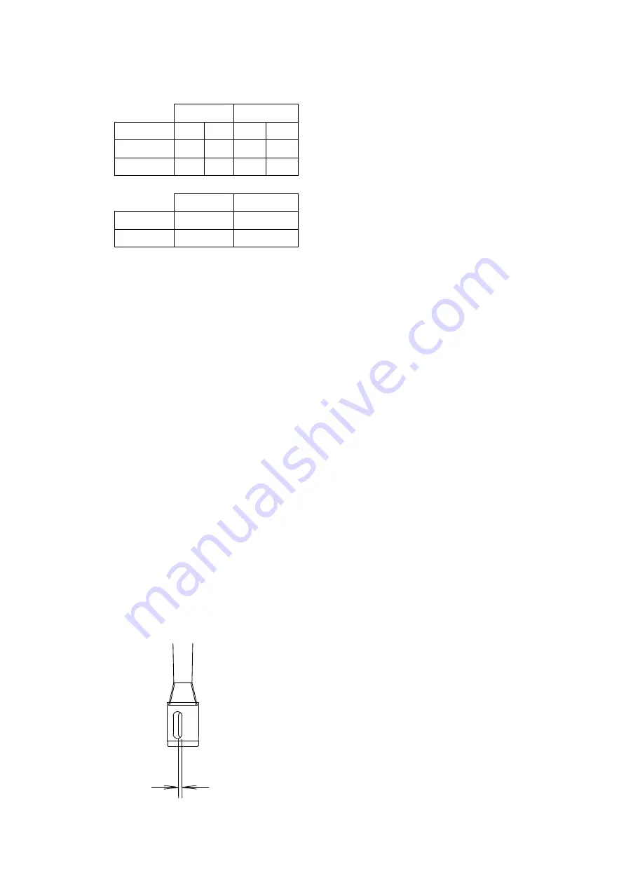
The oven burner has a fixed injector and aeration gap
should be factory set. Check this is as indicated in
Figure 1 and reset if necessary.
7mm
(Natural and Propane)
Figure 1
Oven burner aeration screw is located in burner
throat below loose base panel.
Oven By-Pass Rate
The minimum gas flow to burner is governed by fixed
drilled hole size of thermostat by-pass screw.
The orifice size is ù0.6mm for Natural gas and ù0.4
for Propane operation.
SECTION 2 - ASSEMBLY
andCOMMISSIONING
2.1 ASSEMBLY
Position unit and level using the feet adjusters.
The feet are provided with holes which enable the
unit to be secured to the floor. It is essential to effect
this operation on both models.
Open oven door, pull out shelves and loose base
panel. Check burner, spark igniter and flame failure
arrangements are correctly located and secured.
Replace all parts in reverse sequence.
On G350/1 model, check open-top burner
assemblies, pan supports, spillage deflectors.
Spillage trays may be packed separately inside oven
compartment.
The spillage tray slides through an aperture in front
facia panel below controls (open top models only).
The side spillage deflectors have a raised edge which
engage below fixed side trims.
The burner bodies and injectors are fixed and should
not require adjustment. The burner head fits loosely
on the aluminium bezel which is secured to driptray.
Ensure the lugs and pins are correctly located.
On G350/2 models, check solid topby removing
bullseye and filling plates. Remove loose packing and
replace fillings etc.
2.2 CONNECTION TO THE GAS SUPPLY
The supply piping and unit connection must be
installed in accordance with regulations listed on the
cover of the manual.
On NATURAL GAS units, the adjustable governor
supplied MUST BE FITTED in supply, securely fixed
in a position which enables adjustment to be made
during commissioning. Propane models MUST NOT
be fitted with a governor.
2.3 CONNECTING THE ELECTRICAL SUPPLY
Not applicable to these appliances.
2.4 CONNECTING THE WATER SUPPLY
Not applicable to these appliances.
All manuals and user guides at all-guides.com


