2.5 PRE-COMMISSIONING CHECK
After connecting to gas supply, fit a pressure gauge to
the test point as detailed in Section 1.9). Check entire
installation for gas soundness. Purge air from system
and light burners in accordance with appropriate
section below.
Check pressure on gauge and adjust governor if
necessary. Remove screwed capon governor and
turn screw inside. Clockwise to increase pressure,
and vice-versa.
When satisfied pressure is correct, re-fit governor
cap.
2.5.1 Oven Burner
Check oven burner lights readily from spark igniter
and heat oven at 270
o
C for approximately 20 minutes
before turning knob back to 120
o
C. Observe that
burner flame reduces to by-pass rate. Check oven
burner aeration setting (as detailed in Section 1.10.3).
To Light The Oven Burner
Proceed as follows:
1. Open oven door to gain access to flame-failure
and igniter buttons.
2. Push in and turn thermostat knob anti-clockwise to
the 270
o
C setting
.
3. Push in flame-failure button and keepit pressed in.
4. Push igniter button to light burner. If it does not
light immediately, repeatedly press and release
the button until it does.
5. Continue to push flame-failure button for approx.
15 seconds before release. The flame will now
increase to maximum and oven doors can be
closed. Turn thermostat knob to desired setting.
To Turn the Oven OFF
Push in and turn thermostat knob fully clockwise to
OFF position.
2.5.2 SolidTop Burner
Check that hotplate burner lights readily from pilot.
Check also that thermocouple remains energised
when burner is turned down to low setting on control
tap.
Warning
If pilot is extinguished intentionally or unintentionally,
no attempt to re-light gas should be made until at
least 3 minutes have elapsed.
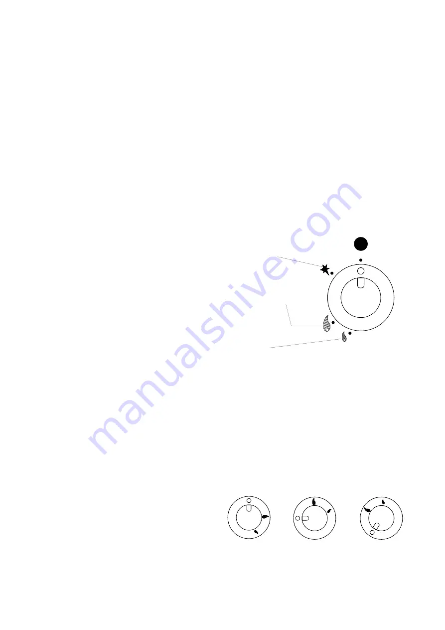
To Light The Burner
Proceed as follows (Refer to Figure 2):
1. Remove centre ring using special tool provided.
2. Have a lit taper or match ready in one hand.
3. With other hand, push in control knob and turn
anti-clockwise until knob mark is opposite ignition
symbol.
4. Light to pilot, keeping knob pushed in.
5. Release knob after approx. 20 seconds, pilot
should remain lit. If not, push knob in and turn
clockwise to OFF position. Wait 3 minutes and
repeat from Step 2.
6. Having established pilot flame, replace centre ring.
7. Push knob in again and turn anti-clockwise to
FULL FLAME symbol to light burner.
8. If desired, burner can be turned to LOW or
SIMMER settings by further depression of knob
and turning fully anti-clockwise to small symbol.
To Turn The Burner OFF
9. To turn off main burner leaving pilot lit, push in
knob and turn to ignition symbol.
10.To turn off main burner and pilot, push in knob and
turn to OFF position.
Note
It will be seen from the above instructions, knob
requires to be pushed in prior to any turning
movement.
Ignition
Full Flame
Low
Flame
Figure 2
2.5.3 Open Top Burner
The gas taps are of the safety type.
To Light A Burner (Refer to Figure 3)
Identify appropriate tap by facia panel marker.
Push tapin and turn anti-clockwise to FULL FLAME
position whilst applying a lit taper or match to rim of
burner head. Hold control knob in for upto 20
seconds in order for flame failure device to engage.
Knob can then be turned further anti-clockwise to
reduce flame if desired.
To Turn The Burner OFF
Simply turn knob clockwise as far as it will go.
OFF
FULL ON
SIMMER
(turn anti-clockwise)
(turn further
anti-
clockwise)
Figure 3
All manuals and user guides at all-guides.com


