SECTION 1 - INSTALLATION
UNLESS OTHERWISE STATED, PARTS
BEEN PROTECTED BY THE MANUFACTURER
NOT TO BE ADJUSTED BY THE INSTALLER.
Please ensure that any plastic coatings are
to use. Before operation, pan requires
cleaned and dried.
Discolouration of heated parts is caused
testing to ensure a satisfactory unit. It
quality or performance.
1.1 MODEL NUMBERS, NETT WEIGHTS
and DIMENSIONS
Model
Width
(mm)
Depth
(mm)
G401F Fryer
400
840
G402F Fryer
400
840
Pan oil capacity:
18 litres cold, good quality oil (to - MIN
1.2 SITING
The unit must be installed on a firm, level
lit draught free position. The fryer should
in a position where the possibility of sideways
likely when force is applied. The means
be the manner of installation, such as
a battery of appliances or installing the fryer
or by separate means, such as adequate
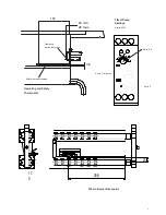
1.2.1 Anti-tipping Accessory
An anti-tipping mechanism is also
accessory. If these are to be fitted, the brackets
fitted to locate the fryer in the correct position
any walls as detailed below. Fixing holes are provided in
the fryer base to accommodate the bracket.
should be fitted as detailed in Figure
chain has a quick release eyelet. Secure
and secure bracket to floor after
anti-tipping device attached to the fryer.
below floor bracket.
Figure 1 - Anti-tipping Bracket
TION
TS WHICH HAVE
MANUFACTURER ARE
INSTALLER.
are removed prior
to be thoroughly
caused by factory
It does not affect
WEIGHTS
Height
(mm)
Weight
(kg)
1200
94
1200
94
MIN - mark)
level floor in a well-
should not be installed
sideways tipping is
means of restraint may
as connection to
fryer in an alcove,
as adequate ties.
available as an
brackets must be
position relative to
holes are provided in
bracket. The bracket
1. The retaining
Secure to fixing point
alignment with
fryer. Adjust to slide
Bracket
1.2.2 Clearances
The unit requires a clearance
between unit and any combustible
A minimum vertical clearance
allowed between top edge
overlying combustible surface.
Important
If fryer is to be installed with
instructions for every model
determine the necessary clearance
wall or overlying surface.
Some appliances require greater
than others. The largest
determine overall distance
adjoining appliances.
1.3 VENTILATION
The appliance ventilation requirements
with national and local regulations.
The ventilation rate for these
The appliance flue discharges
There must be no direct connection
mechanical extraction system
should be installed under a ventilated
Adequate ventilation, whether
be provided to ensure sufficient
and for removal of combustion
harmful to health.
For multiple installations, requirements should
together. Installations should
local and/or national regulations
A competent engineer must
work.
1.4 GAS SUPPLY (Both models)
To be checked at installation,
The SIT gas valve, situated
accessible by removing RH
governor. The inlet pressure
inlet test nipple using a manometer
should be set at test nipple on burner
means of a manometer as
Page 4 (for either natural
achieved by removing brass
governor and adjusting governor
screwdriver - clockwise rotation
Note: Propane requires governor
clockwise to maximum adjustment.
3
clearance of at least 150mm to rear
combustible wall.
clearance of 750mm should be
edge of flue outlet and any
surface.
with other appliances then the
model should be consulted to
clearance to any combustible
greater clearance distances
largest clearance will therefore
for a complete suite of
requirements should be in line
regulations.
these models is 26m³/min.
discharges vertically from top of unit.
connection of flue to any
system or outside air. The fryer
ventilated canopy.
whether natural or mechanical must
sufficient fresh air for combustion
combustion products which may be
requirements should be added
be made in accordance with
regulations applying at the time.
be used for any installation
models)
at installation, gas conversion or repair.
at rear RH side of unit and
RH side, has an in-built
should be checked at valve
a manometer and burner pressure
on burner manifold, again by
as per values indicated on
or propane gas). This is
brass dust screw from valve
governor accordingly using a
rotation increases pressure.
governor to be adjusted
adjustment.
Summary of Contents for G402F
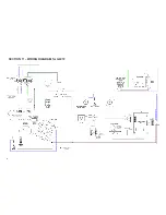
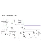
Page 16: ...SECTION 11 WIRING DIAGRAM for G401 16...
Page 17: ...SECTION 11 WIRING DIAGRAM for G401F 17...
Page 18: ...SECTION 11 WIRING DIAGRAM for G402 18...
Page 19: ...SECTION 11 WIRING DIAGRAM for G402F 19...
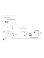
Page 20: ...SECTION 11 CIRCUIT DIAGRAM for G401 20...
Page 21: ...SECTION 11 CIRCUIT DIAGRAM for G401F 21...

