1
F900 SERIES
User, installation and servicing instructions
GAS CHARGRILL
G9440, G9460, G9490, G94120
Read these instructions before use
T100873
DATE PURCHASED:
MODEL NUMBER:
SERIAL NUMBER:
DEALER:
SERVICE PROVIDER:
REV. 4
Published: 23/08/2016
Page 1: ...r installation and servicing instructions GAS CHARGRILL G9440 G9460 G9490 G94120 Read these instructions before use T100873 DATE PURCHASED MODEL NUMBER SERIAL NUMBER DEALER SERVICE PROVIDER REV 4 Publ...
Page 2: ...iance and any replacement parts in a safe manner via a licensed waste handler Appliances are designed to be dismantled easily and recycling of all material is encouraged whenever practicable Dear Cust...
Page 3: ...3 SYMBOLS SPANNER SCREWDRIVER COOKING OIL GREASE SPARK IGNITION FLAME WARNING VIEWPORT ALLEN KEY IGNITER...
Page 4: ...d persons The installer must instruct the responsible person s of the correct operation and maintenance of the appliance Only competent persons are allowed to service or convert the appliance to anoth...
Page 5: ...N LOCATIONS 12 6 0 INSTALLATION 13 6 1 SITING CLEARANCES 13 6 2 VENTILATION 13 6 3 GAS SUPPLY CONNECTION 14 6 4 ASSEMBLY 15 6 5 COMMISSIONING 15 6 6 SUITING 16 7 CONVERSION 18 7 4 GAS CONVERSION CHECK...
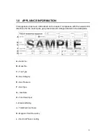
Page 6: ...elevant EU directives for the heat inputs gas pressures and voltages stated on the data plate A Serial No B Model No C Flue Type D Gas Category E Gas Pressure F Gas Type G Gas Rate H Total Heat Input...
Page 7: ...PONENT PARTS A Scraper B Lifting Tool C Brander Bar D Burner Baffle E Splashguard F Burner G Control Knob H Spark Igniter I Drip Tray J Deflector K Fat Jug Not required in G9440 2 2 CONTROLS A Spark I...
Page 8: ...nd out See section 3 2 3 2 Position burner baffles and brander bars correctly A High position B Low position C Burner Baffle D Baffle support E Lightly oil bars 2 3 3 Fill about a 1 3 of the drip tray...
Page 9: ...ars 3 3 Scrape off burnt on food 3 4 Remove other debris using a cloth 3 5 Dry and brush with vegetable oil 3 6 Remove splashguard burner baffles and fat jug and clean 3 7 Wipe burners with a damp clo...
Page 10: ...5 Amal 300 Amal 300 G94120 2 5 Amal 310 Amal 310 Pilot Injectors 31 2 25 25 Supply Pressure mbar 20 29 50 37 Operating Pressure mbar 15 29 37 HEAT INPUTS kW G20 G30 G31 Full Low Full Low Full Low G94...
Page 11: ...11...
Page 12: ...12 5 0 DIMENSIONS CONNECTION LOCATIONS A GAS INLET...
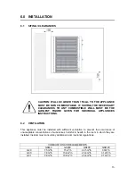
Page 13: ...IONS 6 2 VENTILATION This appliance must be installed with sufficient ventilation to prevent the occurrence of unacceptable concentrations of substances harmful to health in the room in which they are...
Page 14: ...mply with national requirements These must be periodically examined and replaced as necessary If a retention chain is required then attach this to the fixing shown below 6 3 3 Supplied governor must b...
Page 15: ...e 8 6 for governor adjustment 6 5 3 Light all pilots and ensure all stay lit 6 5 4 Turn on main burners Ensure correct cross lighting occurs 6 5 5 Check for flame stability 6 5 6 Operate taps between...
Page 16: ...e hob rear infill and replace with rear suiting plate and fixings 6 6 4 Remove the front side panel countersunk screw and suiting plate NOTE The DLS system is designed to give a quick and easy suiting...
Page 17: ...through the front fixing holes of both units 6 6 8 B Left hand unit Slide the penny and lock washer on to the screw and secure using the M5 nut 6 6 9 C Remove the front bolts from feet insert base ti...
Page 18: ...by turning screw fully clockwise To convert back to Ng ensure screw is turned fully clockwise and then turn screw two complete turns anti clockwise see 8 5 As a reference the flame on turndown should...
Page 19: ...19 8 SERVICING 8 1 BURNERS 8 1 1 Remove burners as shown 8 1 2 Clean burners see section 3 8 1 3 Clean ports...
Page 20: ...20 8 1 4 For conversion adjust aeration shroud as shown...
Page 21: ...ner ensure locating lugs locate in the rear support bar correctly 8 2 INJECTORS 8 2 1 Remove injector as shown 8 2 2 Clean injector 8 2 3 Check washers are clean and serviceable 8 2 4 After replacemen...
Page 22: ...22 8 3 CONTROL PANEL 8 3 1 Remove as shown 8 4 PILOT ASSEMBLY 8 4 1 Remove pilot components as shown A Thermocouple B Pilot gas pipe C Spark electrode D Pilot bracket...
Page 23: ...23 8 5 GAS VALVE 8 5 1 Remove gas valve as shown A Thermocouple B Pilot gas pipe C Main gas pipe D Valve clamp E Bypass screw 8 5 2 Service valve as shown...
Page 24: ...VERNOR 8 6 1 This applies to G20 and G30 50mb models only 1 Gas in 2 Gas out 3 Direction of flow GOVERNOR SUPPLIED IS MAINTENANCE FREE ENSURE THE BLUE DUST CAP COVERING THE VENT IS FITTED AND IN GOOD...
Page 25: ...t Gas pressure too low Check pressure adjust as necessary Injector s blocked or damaged Clear nozzle s or replace Burner ports blocked Clear ports or replace Gas tap s seized or blocked Clear or repla...
Page 26: ...mber Serial number Gas Type This information is found on data plate on front panel See section 1 0 Visit our website for further spares information 11 SERVICE INFORMATION It is recommended to have a m...