-
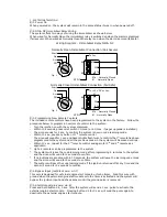
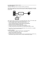
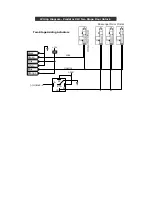
5. Central Locking Wiring
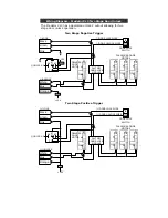
Follow the diagrams below for wiring basic central locking systems
+12V
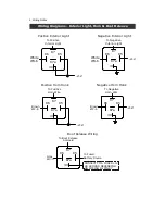
Wiring Diagram - Predator XL3 Door Lock/Unlock - Basic
Black
Green
Pink
White
Blue
Orange
Original Built-in
Controller
Diagram #A
Negative or Positive Locking
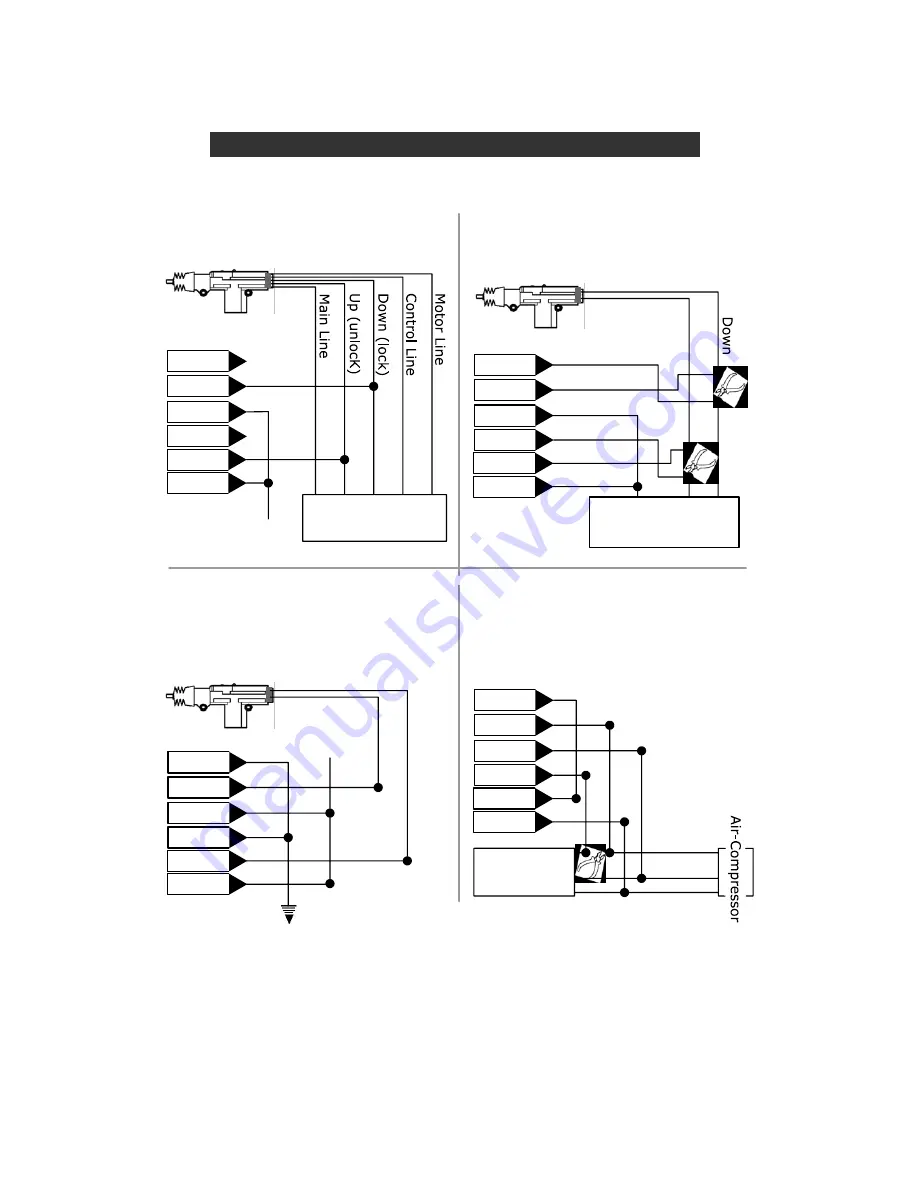
Diagram #B
Motor Interrupt Locking
eg. CHRYSLER
Door Lock Switch
On the Front Door
Black
Green
Pink
White
Blue
Orange
Black
Green
Pink
White
Blue
Orange
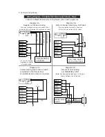
Diagram #C
Central locking where only a switch
is installed in the drivers door.
An additional door motor is required.
Diagram #D
Vacuum central locking
eg: MERCEDES, AUDI
(Note: Set door lock/unlock time to 3.6 sec.)
Black
Green
Pink
White
Blue
Orange
Electric Motor
Switch
Main Line
Down
Up
Up
+12V
Down
Up
To +12V or Ground
Depending on polarity
of locking system
Polarity Reverses on a single wire
Two wires resting at ground, one pulses
12V for lock, one pulses 12V for unlock
Two wires resting open circuit one pulses 12V or
ground for lock, one pulses 12V or ground for unlock


