background image

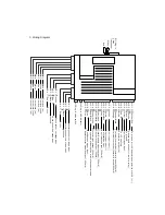
1. SYSTEM INSTALLATION 

1.1. Power On  

When powered on, the system will remain in the same status it was in when powered off. 


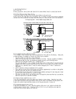
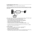
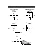
1.2. NO & NC Immobiliser Relay Wiring 

The system offers two ways of wiring the immobiliser as shown below.  

When wired for Normally Open the immobiliser relay is switched on when the alarm is disarmed 
(fail secure). When wired as Normally Closed the relay is on when the alarm is armed (fail safe). 

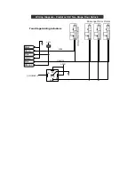
Wiring Diagram - Immobiliser Relay NO & NC

Normally Closed Immobiliser Connection (Fail Safe)

87a - Normally Closed

87 - Normally Open

Off

Acc

On

Start

86

85

87

87a

30

To +12V DC or Acc.

W2-8

fig. 2

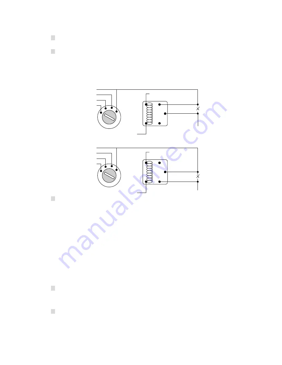
Normally Open Immobiliser Connection (Fail Secure)

87a - Normally Closed

87 - Normally Open

Off

Acc

On

Start

86

85

87

87a

30

To Acc.

W2-7

fig. 1


1.3. Programming New Remote Controls 
The included remote controls have been programmed to the system in the factory.  Follow the 

procedure below to program a new remote control to the system: 

-  Turn the ignition on with the system disarmed. 
-  Within 10 seconds, press valet switch 3 times. (or 6 times  if pager upgrade is installed). 

-  The siren sounds for 2 sec. to confirm the system is now in code learning mode. 

-  Within 10 sec., press any button of 1

st

 remote control 


The siren will sound for 1 sec. and hazard lights flash twice to confirm the 1

st

 remote has been 

programmed to the system and all the previous codes in the system will be erased entirely. 

-  Within 10 sec., repeat for the 2

nd

 remote control and again for 3

rd

 and 4

th

 remotes as 

applicable. 

*  Up to 4 remotes can be programmed to the system 

*  The system will leave the code learning mode after programming 4 remotes to the system 

and the siren will sound for 2 seconds


to confirm. 

*  If no buttons are pressed within 10 seconds, the system will leave the learning code mode 

and the siren will sound for 2 seconds to confirm. 

*  The system will leave the code learning mode if the ignition is turned off at any time and the 

siren will sound for 2 seconds to confirm. 


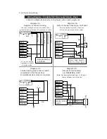
1.4. Bypass Input (red/black wire: w3-7) 

This wire is designed for external engine start module or turbo timer.  Feed this wire with 

ground when the external engine start module or turbo timer is activated and the system will 
bypass the ignition input and shock sensor until the ground pulse is removed.  


1.5. Start Output (pink wire: w3-9) 

Press and hold button #4, 3 sec. later the system will send a 1 sec. pulse to activate the 
external engine start module.  Pressing button #4 for 3 sec. will send the pulse again to 

deactivate the external engine start module.  


Summary of Contents for Predator XL3

Page 1: ...ming New Remote Controls 2 1 4 Bypass Input red black wire w3 7 2 1 5 Start Output pink wire w3 9 2 1 6 Interior Light Supervision green white wire w3 6 3 1 7 Program the Optional Features default 1 c...

Page 2: ...10 sec press any button of 1st remote control The siren will sound for 1 sec and hazard lights flash twice to confirm the 1st remote has been programmed to the system and all the previous codes in th...

Page 3: ...sound for 2 sec to confirm if the ignition is turned off at any time during programming or if the valet switch or remote control button 1 has not been pressed within 10 sec 1 8 Optional Programmable...

Page 4: ...hen Enabled The doors will also be locked when the system passively arms itself 03 Ignition Lock default disabled When set as Ignition The doors will be locked 15 sec after turning the ignition on if...

Page 5: ...en pressing button 2 to disarm the system Pressing button 2 again within 3 seconds will unlock the rest of the doors When set as All All the doors will be unlocked when pressing button 2 to disarm the...

Page 6: ...until the door is closed or the ignition is turned off The feature will not be activated if the door is opened whilst the ignition is on When set as Mode 2 The hazard lights will flash when a door is...

Page 7: ...ry 2 secs once the countdown starts After 30 or 60 sec depending on the selection of feature 16 the system enters the Anti hijacking mode 10 sec before the countdown ends the siren and hazard lights w...

Page 8: ...s in learning mode Turn the vehicles hazard lights on and the hazard lights start to flash Within 10 sec press and hold the valet switch The LED will turn on to confirm the valet switch is pressed Rel...

Page 9: ...trigger input Red W2 5 To 12V battery Brown W2 6 Siren Horn output 1A Orange Black W2 7 Immobiliser output normally open 500mA Orange W2 8 Immobiliser output normally closed 500mA W3 0 Green Door tri...

Page 10: ...erior Light To Positive Interior Light 87 85 86 87a 30 12 White W3 6 87 85 86 87a 30 To Negative Interior Light 12 White W3 6 Positive Horn Honk Negative Horn Honk To Positive Horn Wire 87 85 86 87a 3...

Page 11: ...hite Blue Orange Diagram C Central locking where only a switch is installed in the drivers door An additional door motor is required Diagram D Vacuum central locking eg MERCEDES AUDI Note Set door loc...

Page 12: ...CK 2 DOOR LOCK SWITCH UL L FACTORY DOOR LOCK MODULE PASSENGER DOOR MOTORS DRIVERS DOOR MOTOR DOOR LOCK WIRE DOOR UNLOCK WIRE Black Pink Green LOCK 87 87a 85 86 30 White Blue Orange UNLOCK 12V 15A UNLO...

Page 13: ...Wiring Diagram Predator XL3 Two Stage Door Unlock Two Stage Adding Actuators 12V Black Green Pink White Blue Orange 86 85 87a 30 87 Unlock 2 12V Passenger Door Motors 15A LOCK UNLOCK...

Reviews: