-
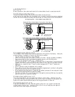
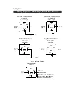
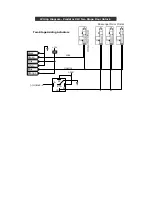
21. Hazard lights Output (default=normal)
When set as Normal:
Connect the hazard lights output as normal using the Y-splitter lead.
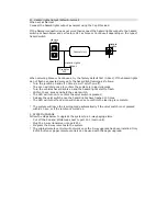
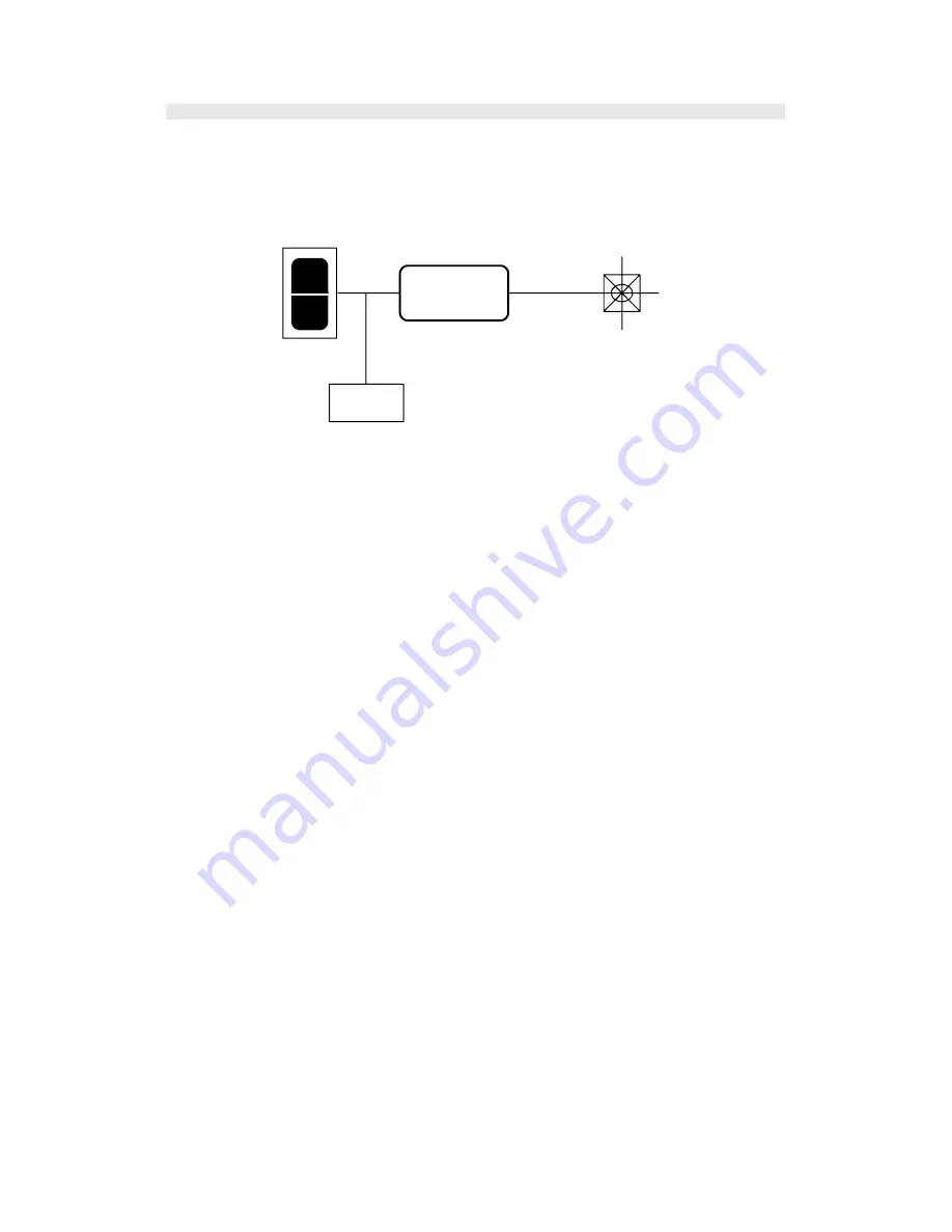
If the Normal connection does not work then connect the hazard lights output to the hazard
switch as shown below and set feature #21 as Pulse or Continuous depending on the type of
hazard switch
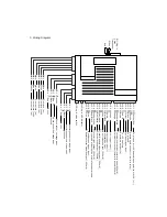
O
I
Control Unit
Predator
XL3
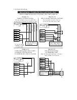
Hazard
Switch
Hazard Lights
Output
Hazard
Lights
When selecting Pulse or Continuous, try the factory default first (0.5sec). If the hazard lights
do not flash as expected proceed to the hazard light learning as follows:
- Turn the ignition on and off 3 times (on-off-on-off-on-off).
- The siren will chirp once to confirm the system is in learning mode.
- Turn the vehicles hazard lights on and the hazard lights start to flash.
- Within 10 sec. press and hold the valet switch.
- The LED will turn on to confirm the valet switch is pressed.
- Release the valet switch once the hazard lights have flashed 10 times.
- The LED will turn off and siren will chirp once to confirm the learning is complete.
* The system will leave the learning mode automatically if the valet switch is not pressed
within 10 sec. or if the ignition is turned on.
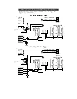
2. SYSTEM UPGRADE
Follow the steps below to upgrade the system to a 2-way paging alarm.
- Cut off the Red and White loops next to port W-1 (main unit).
- Plug the 2-way transceiver into port W-1.
- Program the 2-way remotes to the system.
* The original remote controls will not work once the 2-way upgrade has been installed. Only
EVO 4 button or pager remote controls can be used with the pager upgrade.


