-
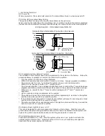
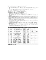
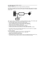
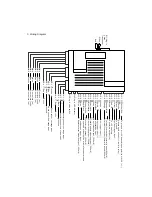
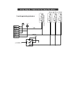
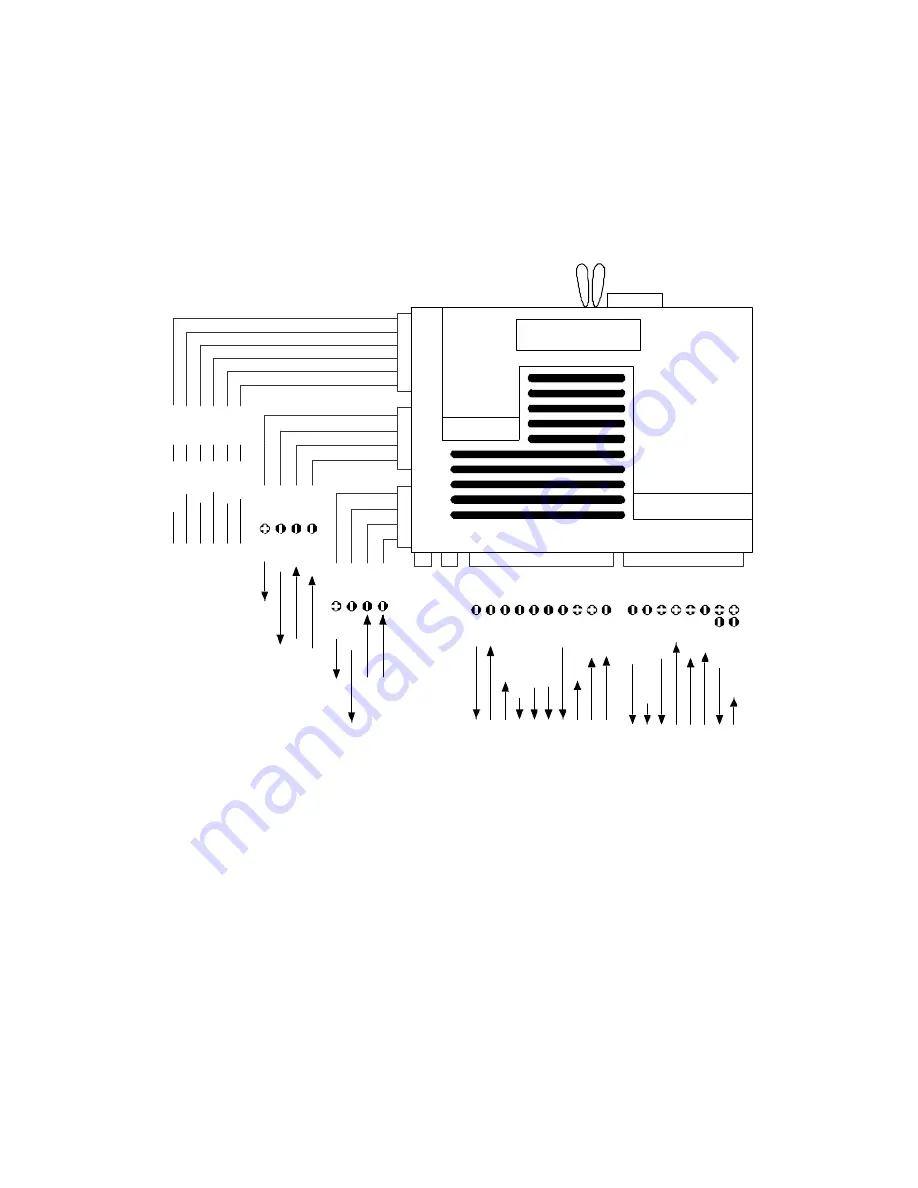
3. Wiring Diagram
Door
l
o
ck (nc)
Black
W8-1
Door
l
o
ck (com)
G
reen
W8-2
Door
l
o
ck (no)
Pink
W8-3
Door
unl
ock (nc)
Whi
te
W8-4
Door
unl
ock (com)
Blue
W8-5
W7-3
Bl
ack
G
ro
und
W7-1
Gr
ee
n
Shock se
nsor
1st stage
i
n
put
W7-2
Bl
ue
Shock se
nsor
2nd stage
i
n
put
W7-4
Red
+12v
W6-3
Bl
ack
G
ro
und
W6-4
Red
+12v
W6-1
A
u
xiliary s
en
so
r 1s
t s
ta
g
e in
p
u
t
W6-2
A
u
xiliary s
en
so
r 2n
d
s
ta
g
e in
p
u
t
To gr
ound or
+12V de
pe
ndi
n
g on pol
ar
ity of W2-2 (+/-)
Whi
te/Red
W2-1
Whi
te
W2-2
H
azard
lig
h
ts
o
u
tp
u
t (
+
/-
b
u
ilt
-in
relay)
Black
W2-3
To gr
ound
Y
ello
w
W2-4
Igni
ti
on tr
igge
r i
n
put
Red
W2-5
To +12V battery
Brown
W2-6
Si
re
n/Hor
n
output (1A)
Orange/Black
W2-7
Immob
ilis
er out
p
ut
(
n
ormally op
en/
-500mA)
Orange
W2-8
Immob
ilis
er out
p
ut
(
n
ormally c
los
ed
/-
500mA)
W3-0
Gr
ee
n
Door
tr
igge
r i
n
put (-)
W3-1
Pur
p
le
Door
tr
igge
r i
n
put (+)
W3-2
Bl
ack/Red
To footbr
ake
l
ig
ht
W3-3
Gr
ay
Boot release output (-500mA)
W3-4
Gr
ay/bl
ack
Total/Comfort closure output (-500mA)
W3-5
Bl
ue
/Whi
te
Door unlock2 output (-500mA)
W3-6
Gr
ee
n
/Whi
te
Interior light output (-500mA)
W3-8
Bl
ue
Boot/Bonne
t tr
igge
r i
n
put
W3-9
Pink
Remote starter mo
dule output (-500mA)
W3-7
Red/Bl
ack
Bypass i
n
put fr
om opti
onal
r
emote
star
te
r modul
e
W5 P
lug-i
n Val
et swi
tch
W
1
-P
lu
g
-in
2Way
Tr
anscei
ver
W4 Pl
ug-i
n LED i
n
di
cator
Whi
te
Red
Door
unl
ock (no)
Orange
W8-6


