background image

34

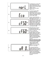
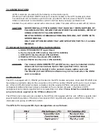
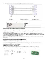
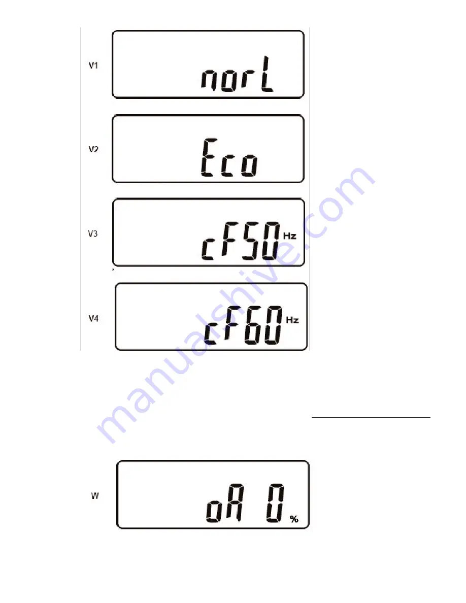
The following V1, V2, V3 and V4
show the operational status 
setting of the UPS. This function
may be set to one of four modes.
“Normal”: which 
indicates none of the other
modes are set.

The Economy/Green Mode: 
indicates the UPS will 
automatically transfer to bypass
mode to save energy, should the
output load drop below 10% of
the UPS output rating. 

Fixed or constant frequency 
output mode: In normal mode the
UPS output frequency will 
automatically be set to the utility
frequency and is synchronized
with that frequency. When set to
cf50Hz mode, the UPS inverter
output frequency will always be
50Hz. When set to cf60Hz mode,
the UPS inverter output frequen-
cy will always be 60Hz.

Setting the UPS to a fixed or 
constant output frequency
should be done when the input
source is a generator.

To change between these
settings, depress the”Previous
Page/Change Setting” button.
Repeat pressing the button until
the desired mode setting is 
displayed. All setting changes
will be saved when prompted at
the end of the parameter
sequence.

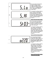
Depress the “Next Page” button.

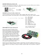
The next parameter displayed
shows the inverter output 
voltage adjustment. The 
adjustment can be set to 0%
(shown), +1%, -1%, +2%, -2%,
+3%or -3% (not shown). 

To change between these
settings, depress the “Previous
Page/Change Setting” button.
Repeat pressing the button until
the desired mode setting is 
displayed. All setting changes
will be saved when prompted at
the end of the parameter
sequence.

Summary of Contents for RACKMOUNT UPS PLUS FN3KRM-2

Page 1: ...2TXI FN8KRM 2 2TX 2TXI FN10KRM 2 2TX 2TXI FALCON Electric Inc 5116 Azusa Canyon Rd Irwindale California 91706 626 962 7770 Fax 626 962 7720 Email sales falconups com 2011 Falcon Electric Inc All right...

Page 2: ...ng Diagram Typical 16 4 15 External Battery Charger Option Installation 19 Chapter 5 Displays Controls 5 1 Control Button and LCD Locations 20 5 2 Control Button Operation 20 5 3 LED Display Modes 21...

Page 3: ...Display with Advanced Monitoring Remote Emergency Power Off REPO Option Input Power Factor Correction Wide Input Voltage Window Precision Output Voltage Regulation Superior Brownout Surge and Transie...

Page 4: ...the UPS in an indoor environment with an ambient temperature range of 32 F to 104 F 0 C to 40 C This UPS is designed for use with industrial scientific or data processing class equipment DO NOT USE TO...

Page 5: ...ration UPS control and programming are easily accessed using pushbuttons located adjacent to the LCD display FN rackmount UPS Battery and Transformer module rear panels have the following features and...

Page 6: ...upply the total input power requirements of all FN Series units being connected including all optional extended battery chargers in addition to any other circuits that may be connected to the panel Pl...

Page 7: ...mode The UPS batteries are being charged whenever the UPS is plugged in turned on and operating from utility power The internal UPS battery charger output is rated at 1 9 amps Static Bypass Function N...

Page 8: ...nstallation Kit 1 Software Interface Cable 1 Owner s Manual 1 Installation Kit FNITRM 2 Rackmount Output Transformer Module 1 Installation kit 2 UPS Communications Interface Cables NOTE If multiple FN...

Page 9: ...sure the maximum life of the batteries operation in an ambient temperature of 68 F to 77 F 20 C to 25 C is recommended OPERATION IN TEMPERATURES ABOVE 77 F 25 C WILL REDUCE BATTERY LIFE 5 The FN Serie...

Page 10: ...ck Screw Torque 20 inch pounds Required Branch Rated input circuit breaker 30A 50A with 3 external battery charger module options installed Required Branch Rated output circuit breaker 30A FN6KRM 2TXI...

Page 11: ...240Vac 3 500W split phase 3 wire plus ground 2 FN5KRM 2TXI Not N 1 7 000W N 1 3 500W 3 FN5KRM 2TXI Not N 1 10 500W N 1 7 000W 4 FN5KRM 2TXI Not N 1 14 000W N 1 10 500W 1 FN6KRM 2TXI Not N 1 Hardwire 1...

Page 12: ...4 5 FN 3kVA to 6kVA Rackmount System Rear Panel Overview 4 6 FN 8kVA to 10kVA Rackmount System Rear Panel Overview 12...

Page 13: ...4 7 3 to 6kVA Output Transformer Module Hardwire Terminal Block Wiring Details 13 4 8 3 to 6kVA UPS Module Hardwire Terminal Block Wiring Details...

Page 14: ...4 9 8 to 10kVA UPS Module Hardwire Terminal Block Wiring Details 4 10 8 to 10kVA Output Transformer Module Hardwire Terminal Block Wiring Details 14...

Page 15: ...nectors on the first and last UPS are connected using the longer of the supplied cables Switch on the termination resis tor dip switch next to the long cable For the transformer module daisy chain the...

Page 16: ......

Page 17: ...4 14 8 to 10kVA System Installation Wiring Diagram typical rackmount UPS system 17...

Page 18: ...nd CB2 on rear panel and leave the unit in bypass mode BPS 3 Press and hold the ON and Next Page button simultaneously until the unit beeps twice and enters programming mode 4 Using the Next Page butt...

Page 19: ...ption Installation Wiring Detail Typical UPS unit with optional FN6KBC 5A 2 5 Amp External Battery Charger Module FN6KBC 5A 2 Battery Charger Module Terminal Block Wiring Details Battery Charger Modul...

Page 20: ...r battery mode depressing this button will silence any audible alarms Off Bypass Button 1 When the UPS is operating in utility or battery mode depressing and holding this button until an audible beep...

Page 21: ...Programming Mode and prompted on the LCD display to SAVE settings pressing this button will save all changed parameters Utility AC Source 1 UPS Input Power Present LED Green Indicates utility power i...

Page 22: ...ay In the event of a utility loss that depletes that battery charge the Low Battery icon is displayed until the batteries have recharged to a reasonable level In the event of a complete battery discha...

Page 23: ...ng temperature is not too high Verify the UPS cooling fan operation Er12 Error code 12 indicates the UPS output is overloaded similar to error code 10 This could indicate the connected equipment excee...

Page 24: ...the following LCD display will be shown NOTE Always allow the UPS to charge its batteries for 8 hours prior to use 5 The UPS will now sequence up to on line mode and display the following Display A i...

Page 25: ...the UPS fails the self test FAIL is displayed alternately with an error code Please note the error code and contact Falcon Service The UPS is now turned on and in on line inverter mode Using an AC vol...

Page 26: ...y inverter or battery mode depress the Off button until the UPS sounds two audible beeps The UPS will switch to static bypass and turn off the inverter The LCD will display OFF or BPS The connected lo...

Page 27: ...tage Depress the Next Page button The r denotes the reading is for utility The arrow under the LINE indicates the reading is for the utility frequency Depress the Next Page button The b denotes the re...

Page 28: ...e battery icon indicates the reading is for the battery voltage Depress the Next Page button The degree C symbol indicates the reading is for the internal UPS temperature Depressing the Next Page butt...

Page 29: ...e alarm buzzer status It is shown here to be turned on If the Previous Page Change Setting button is pressed the audible alarm will be turned off Depressing the button again will turn the alarm back o...

Page 30: ...hown below Depress the Next Page button The next parameter displayed shows acceptable input frequency window The window can be set to 3Hz shown or 1Hz not shown Depress the Next Page button The next p...

Page 31: ...tage adjustment The adjustment can be set to 0 shown 1 1 2 2 3 or 3 not shown Depress the Next Page button The next parameter displayed shows the UPS unit address If only one UPS is being used the add...

Page 32: ...them down until the UPS sounds two beeps The audible alarm status parameter setting will be displayed 32 The audible alarm parameter settings cannot be set in this programming mode Refer to section 6...

Page 33: ...wn To change the settings depress the Previous Page Change Setting button To change to the alternate setting press the button again All setting changes will be saved when prompted at the end of the pa...

Page 34: ...z mode the UPS inverter output frequen cy will always be 60Hz Setting the UPS to a fixed or constant output frequency should be done when the input source is a generator To change between these settin...

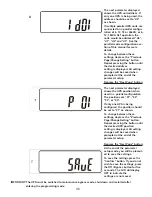
Page 35: ...er displayed shows the UPS position when used in a parallel configuration The positions are 01 02 03 or 04 If only one UPS is being configured the position should be set to 01 as shown To change betwe...

Page 36: ...e the two phillips screws securing the upper and lower sides of the maintenance bypass security cover plate 3 On the rear of the transformer module turn the Maintenance Bypass Switch to Bypass The mai...

Page 37: ...P N UA88380 CAUTION The internal USHA SNMP HTTP AGENT device must be installed into the Advanced Communications Option Slot specified in this manual Do not attempt to install it in the contact closur...

Page 38: ...displayed on the LCD panel After removal of the EPO contact closure the UPS must be completely shut down and restarted to clear the EPO condition 7 4 Optional Communications Interface Board Details UA...

Page 39: ...LINUX 39 1 3 4 2 Pin 1 VCC 5V Pin 2 D Pin 3 D Pin 4 Ground 1 2 3 4 5 6 7 8 9 10 Pin 1 UPS on Bypass Pin 2 Utility Abnormal Pin 3 Utility Normal Pin 4 Inverter On Pin 5 Low Battery Pin 6 Abnormal Batt...

Page 40: ...it is recommended to connect the battery module and turn on the UPS for at least 24 hours every four to six months to ensure full recharging of the batteries This will pre vent excessive battery self...

Page 41: ...alleled The cable kit is shipped with each transformer module inside the shipping container The interface kit contains 1 daisy chain bus cable 3076 1 wrap around bus cable 3077 detailed installation i...

Page 42: ...teries Remove watches rings and other metal objects Use tools with insulated handles Do not lay tools or metal parts on top of batteries Do not attempt to alter any battery wiring or connectors Attemp...

Page 43: ...se the original shipping container and packing materials will likely result in the unit being received by Falcon with shipping damage Falcon Electric will not assume any responsibility for shipping da...

Page 44: ...de of Falcon s control such as fire accidents impacts iv normal wear and tear such as cleaning and replacement of batteries The warranty is null and void if i the product is used in conjunction with l...

Reviews: