6.
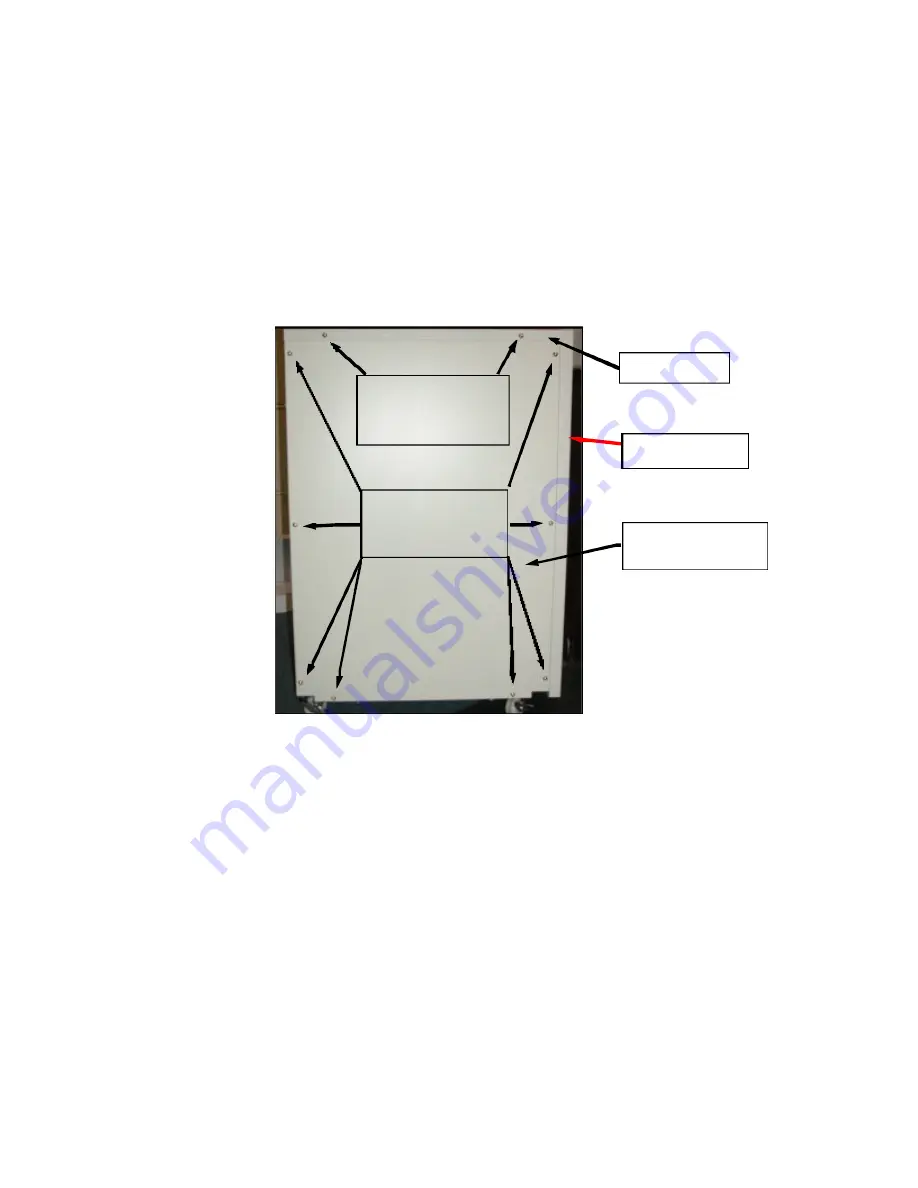
Refer to the picture below. Remove the (4) screws securing the UPS top cover panel,
(2) screws located on each side of the panel. From the edges of the top cover panel
closest to the front panel, lift the top cover panel upward. Some force may be
necessary as the top cover panel is a press-fit over the UPS side panel flanges.
Continue lifting the top cove panel upward until free of the UPS. Set the screws and the
top cover panel aside.
7.
Refer to the picture below. Remove the (8) screws securing the left side panel of the
UPS. Remove the side panel and set aside. Remove the (8) screws securing the right
side panel. Remove the side panel and set aside.
8.
The batteries are located on both sides of the UPS chassis. Please take a few minutes
to acquaint yourself with the positions of the batteries inside the UPS and the photos on
the next page. It is important to locate all of the battery and associated wiring locations
prior to starting the battery removal/installation process.
REMOVE ONE OF THE
SHORT BATTERY INTERCONNECT JUMPERS FROM A BATTERY GROUP ON
EACH SIDE OF THE UPS CHASSIS PRIOR TO PLACING YOUR HANDS INSIDE
THE CHASSIS TO REDUCE THE RISK OF ELECTRICAL SHOCK
.
Top Cover
Panel
UPS Front
Panel
Side Panel
(2 places on both sides
of the UPS)
SIde Cover Screws
(8 places on both sides
of the UPS, 16 screws
total)
Top Cover Screws
(2 places on both sides
of the UPS, 4 screws
total)
TYPICAL UPS & EXTENDED BATTERY BANK
SIDE VIEW
4


