9
UPS Circuit Descriptions
Input Filter
This circuit filters out both electro-magnetic interference (EMI) and radio frequency interference (RFI)
and prevents excessive levels from being conducted back to the utility source. All SSG models have
been tested and comply with FCC Class A requirements.
Input Rectifier & Power Factor Correction
While the UPS is operating from the utility source, this circuit converts utility AC power to regulated DC
power for inverter use. It corrects the input current to maintain a sinusoidal waveform to minimize the
amount of current distortion that will be reflected to the utility.
DC/DC Converter
The DC/DC converter utilizes energy from batteries and boosts up the DC bus voltage to a level
required by the inverter. This allows the inverter to operate continuously at optimum efficiency and
voltage. The converter incorporates a circuit which reduces the amount of ripple current and EMI
interference to the battery, increasing the overall battery life.
DC/AC Inverter
In utility mode operation, the inverter utilizes the regulated DC output to invert DC back into clean,
regulated AC power. When utility power fails, the inverter will receive its energy from the battery
through the DC/DC converter. In both modes of operation, the UPS inverter is online and continuously
generating clean, regulated AC power to the load. The Isolated Gate Bipolar Transistor (IGBT), Pulse
Width Modulation (PWM) inverter design produces a pure sine wave output with a +/-2% voltage
regulation.
Hot-swappable Battery Packs
The SSG UPS utilizes a flame-retardant battery pack comprised of four 12V, 7AH, valve-regulated,
sealed lead acid (VRLA) batteries in each pack. The battery packs are interchangeable between all
SSG 1.5kVA to 6kVA rackmount models. They are easily replaced through the UPS or battery bank
front panel. Optional extended battery banks are available from Falcon.
Battery Charger
The battery charger utilizes energy from the utility power source to continuously charge the UPS
batteries. The UPS batteries are being charged whenever the UPS is plugged in, turned on and
operating from utility power. The internal UPS battery charger output is rated at 1 amp.
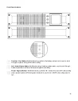
Manual Bypass Function
A manual bypass button is located on the SSG front panel. When the UPS is operating from utility
power in online mode, depressing this button will cause the UPS to transfer to bypass. The bypass
condition transfers the connected equipment to the utility power source via an internal relay. During
bypass condition, the UPS inverter and battery backup operation is disabled. Depressing the bypass
button again will return the UPS to online mode.
Summary of Contents for SSG6KRM-2
Page 2: ...2...
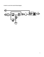
Page 5: ...5 Double Conversion On line UPS Block Diagram...
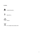
Page 7: ...7 Symbols Important Instruction Special Note Recycle Do not dispose with ordinary trash...
Page 12: ...12 SSGR SSGR 1 2 Models...
Page 25: ...25 SSG6KRM 2TXI With Transformer Module Warning Utility sources must be of the same phase...


