background image

70

Traffic-Control

EN

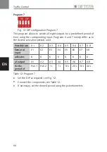
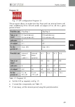
Program 13

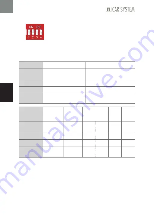
Fig. 18: DIP configuration Program 13

This program allows to realize two flip-flops, two interval timer switches 
and one bus stop, while two additional outputs can be switched on for a 
given period of time.

Possible use

Flip-flop 1

Flip-flop 2

Sensor at 
input

E1 (switches on)
E2 (switches off)

E3 (switches on)
E4 (switches off)

activates

K

K

at output

A1

A3

for the 
period of

max. 40 s

max. 40 s

Possible use

Interval 
timer 
switch 1

Interval 
timer 
switch 2

Bus stop

X 1 

X 2

Sensor at 
input

E5

E6

E7

E8

activates

K

K

ST

AB

K

K

at output

A2

A4

A5

A6

A7

A8

for the 
period of

5 s on 
55 s off

5 s on 
115 s off

Poti 1

1 s

Poti 2

10 s

Table 18: Program 13


X

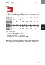
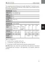
Set the DIP as required, see Fig. 18.


X

Connect the components, see Table 18.


X

If necessary, set the desired period using the potentiometers.

Summary of Contents for 161651

Page 1: ...161651 161654 Traffic Control Traffic Light Control Bedienungsanleitung Instruction Manual DE EN ...

Page 2: ...attG Batteriegesetz 8 3 Produktübersicht 9 Traffic Control 9 Traffic Light Control 11 4 Traffic Control Traffic Light Control anschließen 13 5 Traffic Control 14 Komponenten 14 Traffic Control Programme 17 6 Traffic Light Control 34 7 Was tun wenn 36 8 Wissenswertes 37 9 Technische Daten 41 Elektrische Werte 41 Symbole 41 10 Anhang 83 Einsatzmöglichkeiten Traffic Control 84 Einsatzmöglichkeiten Tr...

Page 3: ... von Sensoren aus Für die Schaltung dieser Funktionselemente ist die Traffic Control mit 15 unterschiedlichen Programmen ausgestattet die Sie bequem über einen Mikroschalter aus wählen können Je nach Programm können Sie voreingestellte Aktivierungs zeiten für die Schaltvorgänge nutzen oder diese über einen Potentiometer individuell einstellen Mit der Traffic Light Control sorgen Sie immer für das ...

Page 4: ...e ein gesetzt zu werden Verwenden Sie das Produkt nur im Innenbereich und vermeiden Sie Witterungseinflüsse Jede andere Verwendung gilt als nicht bestimmungsgemäß Für Schäden oder Mängel die hierdurch oder durch Nichtbeachtung der Bedienungsanleitung entstehen übernimmt die Gebr FALLER GmbH keine Haftung Betriebs und Lagerbedingungen X X Halten Sie folgende Betriebsbedingungen ein 15 C 40 C bis 75...

Page 5: ...sorischen oder mentalen Fähigkeiten oder einem Mangel an Erfahrungen und Wissen benutzt werden wenn sie beaufsichtigt oder diesbezüglich des sicheren Gebrauchs des Produkts unterwiesen wurden und die daraus resultierenden Gefahren verstehen Reinigung und Benutzerwartung dürfen nicht von Kindern ohne Beaufsichtigung durchgeführt werden X X Informieren Sie ggf Kinder über den Inhalt der Bedienungsan...

Page 6: ...Netzspannung X X Produkt bei Schmorgeruch oder Rauchentwicklung sofort von der Span nungsversorgung trennen X X Akkus nicht gewaltsam öffnen oder ins Feuer werfen X X Akkus nicht verpolen X X Akkus nur mit dem vom Hersteller empfohlenen Ladegerät laden X X Akkus niemals überladen Halten Sie unbedingt die angegebenen Lade zeiten ein X X Laden Sie nur vollständig entladene Akkus wieder auf X X Wenn ...

Page 7: ... vollständig und sicher vom Stromnetz zu trennen zie hen Sie den Netzstecker aus der Netzsteckdose WEEE Hinweis Umweltgerecht entsorgen Produkte die mit einem durchgestrichenen Mülleimer Symbol gekennzeich net sind dürfen am Ende ihrer Lebensdauer nicht über den normalen Haus haltsabfall entsorgt werden sondern müssen an einem Sammelpunkt für das Recycling von elektrischen und elektronischen Gerät...

Page 8: ...stoffe wie z B Eisen Zink Man gan oder Nickel und können verwertet werden Sie können die Batterien nach Gebrauch entweder an uns zurücksenden oder in unmittelbarer Nähe z B im Handel oder in kommunalen Sammelstellen unentgeltlich zurück geben Die Abgabe in Verkaufsstellen ist dabei für Endnutzer auf die übli chen Mengen sowie solche Altbatterien beschränkt die der Vertreiber als Neubatterien in se...

Page 9: ...9 Produktübersicht DE 3 Produktübersicht Traffic Control Lieferumfang Traffic Control Art 161651 Bedienelemente Abb 1 Traffic Control Art 161651 ...

Page 10: ...ng von Komponenten als Aus gangssignal Ausgänge 1 8 P1 P2 Zur Einstellung der Zeit für die ein Ausgang aktiviert wird DIP Schalter Beschreibung 1 4 Auswahl der Programme LEDs Beschreibung A1 A8 Zeigt welcher Ausgang aktiv ist Tab 1 Bedienelemente Potentiometer Poti Dreh winkel 0 35 75 105 135 175 210 260 270 Dauer in sec 1 s 2 s 3 s 4 s 5 s 10 s 20 s 30 s 35 s Tab 2 Potentiometer Poti Nähere Erläu...

Page 11: ...11 Produktübersicht DE Traffic Light Control Lieferumfang Traffic Light Control Art 161654 Bedienelemente Abb 2 Traffic Light Control Art 161654 ...

Page 12: ...2 RT GE GN Ampel 1 Anschluss der Ampeln 1 RT GE GN Ampel 2 Anschluss der Ampeln 2 P1 Zur Einstellung der Dauer der Grünphase der Ampeln 1 P2 Zur Einstellung der Dauer der Grünphase der Ampeln 2 L1 L8 Anschluss von Lauflichtern z B Art 161830 LEDs Beschreibung A1 A2 Zeigt welcher Ausgang aktiv ist Tab 3 Bedienelemente Potentiometer Poti Dreh winkel 0 35 75 105 135 175 210 260 270 Dauer in sec 1 s 2...

Page 13: ...selspannung betrieben Die notwendige Spannung können Sie zum Beispiel mit dem FALLER Transformator 50 VA 50 60 Hz Art 180641 erzeugen TIPP Abb 3 Traffic Control Traffic Light Control anschließen X X Schließen Sie die Traffic Control Traffic Light Control an 16 V Wech selspannung an siehe Abb 3 X X Die Traffic Control Traffic Light Control ist an die Stromversorgung angeschlossen ...

Page 14: ...dard Funktionselemente mit denen Sie den Car System Verkehr auf Modellanlagen regeln Während die drei Funkti onselemente Abzweigung Stopp Stelle und Parkplatz an die Aus gänge der Traffic Control angeschlossen werden erfolgt der Anschluss der Sensoren an die Eingänge der Traffic Control Alternativ dazu können Sie auch Schalter und Taster als Eingangssignale verwenden Jede Komponente ist mit zwei K...

Page 15: ...s Parkplatzes wird dieses Magnetfeld kurzfristig durch eine integrierte Elekt rospule überlagert Dadurch wird der Reed Sensor im Fahrzeug geschlossen und der Motor mit Strom versorgt Das Fahrzeug setzt sich in Bewegung Sensoren Art 161773 In die Straße eingelassene Sensoren werden durch Magnete an den Fahr zeugen beim Überfahren aktiviert und geben darüber punktgenau Rückmel dung an die Traffic Co...

Page 16: ... gelbe Kabel der Stopp Stelle muss jeweils an das braune Kabel jeweils an den entsprechenden Ausgang z B A1 angeschlossen werden Test Der Lenkschleifer eines Fahrzeugs wird bei Berührung mit einer aktivierten und richtig gepolten Stopp Stelle von dieser abgestoßen Tauschen Sie im Falle einer Verpolung die bei den Anschlussleitungen Weitere Hinweise zur Behebung von Fehlermel dungen finden Sie in d...

Page 17: ...Control Abb 5 DIP Schalter Die den einzelnen Programmen zugeordneten Schaltabläufe werden Ihnen in den Tabellen auf den nachfolgenden Seiten aufgezeigt Sie finden dar unter einfache Schaltvorgänge die lediglich nach Zeit variieren aber auch komplexere Schaltvorgänge die mehrere Ein und Ausgänge miteinschlie ßen wie etwa bei einer Bushaltestelle oder einem Bahnübergang Verwendete Abkürzungen Machen...

Page 18: ...Die Programme 1 4 unterscheiden sich lediglich in den ver schiedenen Aktivierungszeiten Einsatz möglichkeit Bushalte stelle 1 Bushalte stelle 2 X 1 X 2 X 3 X 4 Sensor an Eingang E1 E2 E3 E4 E5 E6 E7 E8 aktiviert ST AB ST AB K K K K an Ausgang A1 A2 A3 A4 A5 A6 A7 A8 für Dauer Poti 1 1 s Poti 2 1 s 1 s 5 s 10 s 15 s Tab 6 Programm 1 X X Stellen Sie den DIP ein siehe Abb 6 X X Schließen Sie die Komp...

Page 19: ... sich lediglich in den ver schiedenen Aktivierungszeiten Einsatz möglichkeit Bushalte stelle 1 Bushalte stelle 2 X 1 X 2 X 3 X 4 Sensor an Eingang E1 E2 E3 E4 E5 E6 E7 E8 aktiviert ST AB ST AB K K K K an Ausgang A1 A2 A3 A4 A5 A6 A7 A8 für Dauer Poti 1 1 s 15 s 1 s Poti 2 10 s 15 s 20 s Tab 7 Programm 2 X X Stellen Sie den DIP ein siehe Abb 7 X X Schließen Sie die Komponenten an siehe Tab 7 X X St...

Page 20: ...n sich lediglich in den ver schiedenen Aktivierungszeiten Einsatz möglichkeit Bushalte stelle 1 Bushalte stelle 2 X 1 X 2 X 3 X 4 Sensor an Eingang E1 E2 E3 E4 E5 E6 E7 E8 aktiviert ST AB ST AB K K K K an Ausgang A1 A2 A3 A4 A5 A6 A7 A8 für Dauer Poti 1 1 s 20 s 1 s Poti 2 1 s 5 s 10 s Tab 8 Programm 3 X X Stellen Sie den DIP ein siehe Abb 8 X X Schließen Sie die Komponenten an siehe Tab 8 X X Ste...

Page 21: ... sich lediglich in den ver schiedenen Aktivierungszeiten Einsatz möglichkeit Bushalte stelle 1 Bushalte stelle 2 X 1 X 2 X 3 X 4 Sensor an Eingang E1 E2 E3 E4 E5 E6 E7 E8 aktiviert ST AB ST AB K K K K an Ausgang A1 A2 A3 A4 A5 A6 A7 A8 für Dauer Poti 1 1 s 15 s 1 s Poti 2 1 s 15 s 20 s Tab 9 Programm 4 X X Stellen Sie den DIP ein siehe Abb 9 X X Schließen Sie die Komponenten an siehe Tab 9 X X Ste...

Page 22: ...elle 2 Bushalte stelle 3 Bushalte stelle 4 Sensor an Eingang E1 E2 E3 E4 E5 E6 E7 E8 aktiviert ST AB ST AB ST AB ST AB an Ausgang A1 A2 A3 A4 A5 A6 A7 A8 für Dauer Poti 1 1 s Poti 2 1 s 15 s 1 s 20 s 1 s Tab 10 Programm 5 X X Stellen Sie den DIP ein siehe Abb 10 X X Schließen Sie die Komponenten an siehe Tab 10 X X Stellen Sie ggf die gewünschte Dauer mit Hilfe der Potis ein ...

Page 23: ... lediglich in den verschiedenen Aktivierungszeiten Einsatz möglichkeit X 1 X 2 X 3 X 4 X 5 X 6 X 7 X 8 Sensor an Eingang E1 E2 E3 E4 E5 E6 E7 E8 aktiviert K K K K K K K K an Ausgang A1 A2 A3 A4 A5 A6 A7 A8 für Dauer Poti 1 Poti 2 1 s 1 s 5 s 10 s 15 s 20 s Tab 11 Programm 6 X X Stellen Sie den DIP ein siehe Abb 11 X X Schließen Sie die Komponenten an siehe Tab 11 X X Stellen Sie ggf die gewünschte...

Page 24: ...lediglich in den verschiedenen Aktivierungszeiten Einsatz möglichkeit X 1 X 2 X 3 X 4 X 5 X 6 X 7 X 8 Sensor an Eingang E1 E2 E3 E4 E5 E6 E7 E8 aktiviert K K K K K K K K an Ausgang A1 A2 A3 A4 A5 A6 A7 A8 für Dauer Poti 1 Poti 2 1 s 1 s 10 s 20 s 30 s 40 s Tab 12 Programm 7 X X Stellen Sie den DIP ein siehe Abb 12 X X Schließen Sie die Komponenten an siehe Tab 12 X X Stellen Sie ggf die gewünschte...

Page 25: ...rkharfe 2 X 1 X 2 X 3 X 4 Sensor Taster an Eingang E1 E2 E3 E4 E5 E6 E7 E8 aktiviert AB P FR AB P FR K K K K an Ausgang A1 A2 A3 A4 A5 A6 A7 A8 für Dauer 1 s 2 s 1 s 2 s Poti 1 Poti 2 10 s 15 s Tab 13 Programm 8 X X Stellen Sie den DIP ein siehe Abb 13 X X Schließen Sie die Komponenten an siehe Tab 13 X X Stellen Sie ggf die gewünschte Dauer mit Hilfe der Potis ein HINWEIS Bitte beachten Sie auch ...

Page 26: ...atz möglichkeit Parkharfe 1 Parkharfe 2 Parkharfe 3 Parkharfe 4 Sensor Taster an Eingang E1 E2 E3 E4 E5 E6 E7 E8 aktiviert AB P FR AB P FR AB P FR AB P FR an Ausgang A1 A2 A3 A4 A5 A6 A7 A8 für Dauer 1 s 2 s 1 s 2 s 1 s 2 s 1 s 2 s Tab 14 Programm 9 X X Stellen Sie den DIP ein siehe Abb 14 X X Schließen Sie die Komponenten an siehe Tab 14 ...

Page 27: ...ert Über die weiteren Eingänge können die Parkspu ren auf Wunsch auch wieder freigegeben werden Einsatz möglichkeit Zeitmes sung Fahrspuraufteilung nach Fahrzeug geschwindigkeit Akkukapazität Sensor Taster an Eingang E1 E3 E2 E4 E6 E8 aktiviert AB 1 AB 2 AB 3 AB 4 P FR 1 P FR 2 P FR 3 P FR 4 an Ausgang A1 A3 A5 A7 A2 A4 A6 A8 für Dauer Poti 1 2s 3s 4s 5s 2s 2 s 2 s 2 s Tab 15 Programm 10 X X Stell...

Page 28: ...nge können die Parkspu ren auf Wunsch auch wieder freigegeben werden Zusätzlich schalten E5 E8 die Ausgänge A5 A8 für eine definierte Zeit Einsatz möglichkeit Zeitmessung Fahrspuraufteilung nach Fahrzeug geschwindigkeit Akkukapazität Sensor Taster an Eingang E1 E3 E2 E4 aktiviert AB 1 AB 2 P FR 1 P FR 2 an Ausgang A1 A3 A2 A4 für Dauer Poti 1 2 s 3 s 2 s 2 s Einsatz möglichkeit X 1 X 2 X 3 X 4 Sen...

Page 29: ...E2 schaltet aus E3 schaltet ein E4 schaltet aus aktiviert K K an Ausgang A1 A3 für Dauer max 40 s max 40 s Einsatz möglichkeit Intervall schalter 1 Intervall schalter 2 X 1 X 2 X 3 X 4 Sensor an Eingang E5 E6 E7 E8 aktiviert K K K K K K an Ausgang A2 A4 A5 A6 A7 A8 für Dauer 5 s an 55 s aus 5 s an 115 s aus Poti 1 Poti 2 1 s 10 s Tab 17 Programm 12 X X Stellen Sie den DIP ein siehe Abb 17 X X Schl...

Page 30: ...chaltet aus E3 schaltet ein E4 schaltet aus aktiviert K K an Ausgang A1 A3 für Dauer max 40 s max 40 s Einsatz möglichkeit Intervall schalter 1 Intervall schalter 2 Bushaltestelle X 1 X 2 Sensor an Eingang E5 E6 E7 E8 aktiviert K K ST AB K K an Ausgang A2 A4 A5 A6 A7 A8 für Dauer 5 s an 55 s aus 5 s an 115 s aus Poti 1 1 s Poti 2 10 s Tab 18 Programm 13 X X Stellen Sie den DIP ein siehe Abb 18 X X...

Page 31: ...t Stopp Stelle 3 der dazugehörige Aus gang ist A8 Das erste Auto das sich dem Bahnübergang nähert überfährt z B den Sensor an E7 und fährt vor bis zur Haupt Stopp Stelle unmittelbar am Bahnübergang Ist der Bahnübergang aktiv wird durch das Überfah ren von E7 die Stopp Stelle 2 aktiviert sodass ein nachfolgendes Fahrzeug an der zurückversetzten Stopp Stelle stehen bleibt Wichtig hierbei ist dass de...

Page 32: ...X X Stellen Sie ggf die gewünschte Dauer mit Hilfe der Potis ein Programm 15 Abb 20 DIP Stellung Programm 15 Mit diesem Programm können Sie einen kompletten Bahnübergang darstel len Im Unterschied zu Programm 14 besteht die Möglichkeit bis zu 3 Fahr zeuge hintereinander am Bahnübergang warten zu lassen Die Eingänge E3 E8 und die Ausgänge A2 A8 bilden gemeinsam diesen Bahn übergang Die Verzögerungs...

Page 33: ...g A1 für Dauer max 40 s Einsatz möglichkeit Bahnübergang Sensor an Eingang E3 Zug kontakt Anfang E4 Zug kontakt Ende E5 E6 E7 E8 aktiviert HST BL 1 BL 2 ST 2 ST 3 ST 4 ST 5 an Ausgang A3 A2 A4 A5 A6 A7 A8 für Dauer Poti 1 Poti 2 Tab 20 Programm 15 X X Stellen Sie den DIP ein siehe Abb 20 X X Schließen Sie die Komponenten an siehe Tab 20 X X Stellen Sie ggf die gewünschte Dauer mit Hilfe der Potis ...

Page 34: ...ispiel Ampel und Stopp Stellen an die Traffic Light Control anschließen Abb 21 Ampel und Stopp Stellen anschließen X X Schließen Sie die farbigen Leitungen der Ampel an der vorgesehenen Position an Rotes Kabel an RT gelbes Kabel an GE grünes Kabel an GN siehe Abb 21 X X Schließen Sie die schwarze Leitung der Ampel an an siehe Abb 21 Die Ampel ist angeschlossen X X Schließen Sie die Kabel der Stopp...

Page 35: ...Sie die roten Leitungen der Warnlichtbaken an an siehe Abb 22 Die Warnbaken sind angeschlossen HINWEIS Die an L1 bis L8 angeschlossenen Warnlichtbaken blinken spä ter der Reihe nach auf HINWEIS Bitte beachten Sie auch die Tabelle 22 Elektrische Werte im Kapitel 9 Technische Daten dieser Anleitung Zahlreiche Beispiele mit unterschiedlichen Einsatzmöglichkeiten der Traffic Control und der Traffic Li...

Page 36: ...amm passt nicht zum Aufbau X X Prüfen Sie die Programm auswahl Nicht funktio nierende Kom ponenten Falscher Anschluss Beschädigte Kom ponente X X Prüfen Sie den richtigen Anschluss der Komponenten X X Tauschen Sie die Kompo nente aus Fahrzeug hält nicht zuver lässig an einer Stopp Stelle Anschluss falsch gepolt X X Anschlussleitungen tau schen Tab 21 Was tun wenn Der direkte Draht zum FALLER Kunde...

Page 37: ...r einen Sensor oder Schalter der an einen Eingang E1 E2 und an der Traffic Control angeschlossen wird Die Zuordnung der beiden Kabel spielt hierbei keine Rolle Es darf allerdings keine Stromquelle an einen Eingang der Traffic Con trol angeschlossen werden HINWEIS Alle Eingänge sind potentialfrei geschaltet d h dass an ihnen keine Spannung anliegen darf Verwenden Sie zur Aktivierung lediglich Senso...

Page 38: ...verändern Sie mechanisch dessen Widerstandswerte Auf diese Weise können Sie bei den meisten Programmen die Dauer regeln für die ein Ausgang Ihrer Traffic Control oder Traffic Light Control aktiviert ist Der Drehwinkel bewegt sich zwischen 0 unten rechts und 270 oben rechts 0 entsprechen der am kürzesten einstellbaren Dauer von 1 sec während 270 der am längsten einstellbaren Dauer von 35 sec entspr...

Page 39: ...einem Tropfen Sekundenkleber in der Bohrung Positionie ren Sie dabei die flache Kante an der ansonsten runden Sensorenoberfläche quer zur Fahrtrichtung Führen Sie die Fahrdrahtenden von beiden Seiten bis direkt an den Sensor heran HINWEIS Vermeiden Sie den Einbau von Sensoren in Kurven Zusatzmagnete Für den Fall dass nicht jedes Fahrzeug eine bestimmte Komponente akti vieren soll können Sensoren a...

Page 40: ...erboden N FALLER Laser Street ermöglicht Ihnen nahezu jede gewünschte Stra ßenführung Die steckbaren Straßenelemente erhalten Sie mit vorge fräster Nut für die Aufnahme des Fahrdrahts mit Vorbohrungen für Sensoren und Abzweigungen sowie mit Markierungen für die exakte Positionierung von Stopp Stellen Noch nie war es so leicht belebte Straßen zu bauen TIPP Reed Sensor Reed Sensor Zusatzmagnet Zusat...

Page 41: ... Traffic Light Control 800 mA Ausgangsspannung Traffic Light Control A1 A2 ca 22 V DC Ausgangsstrom Traffic Light Control A1 A2 in Summe max 650 mA Ausgangsstrom Traffic Light Control pro LED ca 20 mA Tab 22 Elektrische Werte Symbole Symbol Bedeutung Das Produkt unterliegt der europäi schen WEEE Richtlinie CE Konformitätskennzeichen RoHS CE Konformität inkl RoHS Richtlinie EMC tested CE Konformitä...

Page 42: ...s regarding Batteries 48 3 General view of product 49 Traffic Control 49 Traffic Light Control 51 4 Connecting Traffic Control Traffic Light Control 53 5 Traffic Control 54 Components 54 Traffic Control programs 57 6 Traffic Light Control 74 7 How to deal with problems 76 8 Interesting facts 77 9 Technical data 81 Power supply 81 Symbols 81 10 Appendix 83 Possible use of Traffic Control 84 Possibl...

Page 43: ...nal elements the Traffic Control is fitted with 15 different programs that can easily be selected via a microswitch Depen ding on the program selected you can make use of preset activation times for the various switching procedures or independently set them by means of a particular potentiometer The Traffic Light Control in its turn will always make the right traffic light available at the right t...

Page 44: ...ll be considered not to be in conformity with the proper use or intended purpose Gebr FALLER GmbH will assume no responsibility for any damage or defect resulting from improper use or the non observance of the directions given in the present Instruction Manual Operating and storage conditions X X Observe the following operating conditions 15 40 C up to 75 rela tive humidity do not allow the format...

Page 45: ...tal capabilities or by persons lacking experience or know ledge if they work under supervision or have been instructed in the safe use of the product and understand the hazards resulting from such acti vity Cleaning and maintenance may not be carried out by children wit hout the supervision of adults X X Inform children of the contents of the instruction manual if necessary and of the potential ha...

Page 46: ...onnect the product from the power supply if smoke or a scorching smell is generated X X Never open rechargeable batteries by force or throw them into fire X X Do not short circuit rechargeable batteries X X Recharge storage batteries using only the charging unit recommended by the manufacturer X X Never overload rechargeable batteries Imperatively observe the loa ding times specified X X Only rech...

Page 47: ... reliably from the power sup ply pull the power plug out of the receptacle Environmentally friendly disposal WEEE Products that are labeled with the symbol of a crossed dustbin must not at the end of their life span be disposed of with common household waste but must be handed over to a collecting point that recycles electrical and electronic equipment The symbol on the product in the instruction ...

Page 48: ... as for instance iron zinc manganese or nickel that can be recycled After use consumers may return batteries free of charge either to us or in their nearest vicinity e g in local shops or at municipal collecting points On doing so any return by end users at selling points is limited to the usual quantities and to such used batteries that the distributor carries or has carried in stock as new batte...

Page 49: ...49 General view of product EN 3 General view of product Traffic Control Article supplied Traffic Control Art 161651 Operating elements Fig 1 Traffic Control Art 161651 ...

Page 50: ...ing an output signal Outputs 1 to 8 P1 P2 To set the period of time during which an output is activated DIP switch Description 1 4 Selection of programs LEDs Description A1 A8 Indicates which output is working Table 1 Operating elements Potentiometer Poti Angle of rotation 0 35 75 105 135 175 210 260 270 Duration in seconds 1 s 2 s 3 s 4 s 5 s 10 s 20 s 30 s 35 s Table 2 Potentiometer Poti You wil...

Page 51: ...51 General view of product EN Traffic Light Control Article supplied Traffic Light Control Art 161654 Operating elements Fig 2 Traffic Light Control Art 161654 ...

Page 52: ...ort for traffic lights 1 RT GE GN Ampel 2 Port for traffic lights 2 P1 To set the duration of the green phase at traffic lights 1 P2 To set the duration of the green phase at traffic lights 2 L1 L8 Ports for running lights for example Art 161830 LEDs Description A1 A2 Indicates which output is working Table 3 Operating elements Potentiometer Poti Angle of rota tion 0 35 75 105 135 175 210 260 270 ...

Page 53: ...er nating current The required alternating voltage can be generated by means of FALLER 50 VA 50 to 60 Hz transformer Art 180641 for instance TIP Fig 3 Connecting Traffic Control Traffic Light Control X X Connect Traffic Control Traffic Light Control to 16 V alternating cur rent see Fig 3 X X The Traffic Control Traffic Light Control unit is now connected to its supply voltage ...

Page 54: ...the standard functional elements that will allow you to regulate Car System traffic on model installations While the three functio nal elements that are Branch off junction Stop section and Parking space are connected to the outputs of the Traffic Control unit sensors are connected to the inputs of that unit Alternatively you may also want to use switches and push buttons for input signals Each co...

Page 55: ...ivated that field of force is briefly overlaid with that of a built in current operated coil This closes the dry reed sensor located in the vehicle the motor is supplied again with current from the rechargeable bat tery This sets the vehicle in motion Sensors Art 161773 Sensors built into the roadway are activated by magnets installed on the vehicles and timely send a checkback signal to the contr...

Page 56: ...section component the polarity of the supply cables is quite relevant The yellow cable of the stop section must be con nected to the brown cable to the corresponding output e g A1 In case of reversed polarity just exchange both supply cables You will find further advice relating to the elimination of error messages in the present instruction manual in chapter 7 How to deal with problems The ideal ...

Page 57: ...ll be presented in the tables reproduced in the pages that follow You will find among them a few simple switching operations that merely differ as to the periods of time used but also more complex switching operations that involve several inputs and outputs such as for instance a bus stop or a level crossing Abbreviations used First familiarize yourself with the definitions of the abbreviations us...

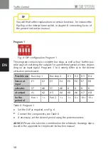
Page 58: ...ding on an input signal Programs 1 to 4 merely differ as to the diverse activation periods used Possible use Bus stop 1 Bus stop 2 X 1 X 2 X 3 X 4 Sensor at input E1 E2 E3 E4 E5 E6 E7 E8 activates ST AB ST AB K K K K at output A1 A2 A3 A4 A5 A6 A7 A8 for the period of Poti 1 1 s Poti 2 1 s 1 s 5 s 10 s 15 s Table 6 Program 1 X X Set the DIP as required see Fig 6 X X Connect the components see Tabl...

Page 59: ...rams 1 to 4 merely differ as to the diverse activation periods used Possible use Bus stop 1 Bus stop 2 X 1 X 2 X 3 X 4 Sensor at input E1 E2 E3 E4 E5 E6 E7 E8 activates ST AB ST AB K K K K at output A1 A2 A3 A4 A5 A6 A7 A8 for the period of Poti 1 1 s 15 s 1 s Poti 2 10 s 15 s 20 s Table 7 Program 2 X X Set the DIP as required see Fig 7 X X Connect the components see Table 7 X X If necessary set t...

Page 60: ...grams 1 to 4 merely differ as to the diverse activation periods used Possible use Bus stop 1 Bus stop 2 X 1 X 2 X 3 X 4 Sensor at input E1 E2 E3 E4 E5 E6 E7 E8 activates ST AB ST AB K K K K at output A1 A2 A3 A4 A5 A6 A7 A8 for the period of Poti 1 1 s 20 s 1 s Poti 2 1 s 5 s 10 s Table 8 Program 3 X X Set the DIP as required see Fig 8 X X Connect the components see Table 8 X X If necessary set th...

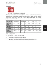
Page 61: ...grams 1 to 4 merely differ as to the diverse activation periods used Possible use Bus stop 1 Bus stop 2 X 1 X 2 X 3 X 4 Sensor at input E1 E2 E3 E4 E5 E6 E7 E8 activates ST AB ST AB K K K K at output A1 A2 A3 A4 A5 A6 A7 A8 for the period of Poti 1 1 s 15 s 1 s Poti 2 1 s 15 s 20 s Table 9 Program 4 X X Set the DIP as required see Fig 9 X X Connect the components see Table 9 X X If necessary set t...

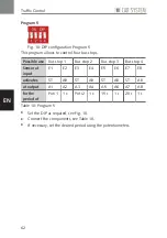
Page 62: ...Bus stop 3 Bus stop 4 Sensor at input E1 E2 E3 E4 E5 E6 E7 E8 activates ST AB ST AB ST AB ST AB at output A1 A2 A3 A4 A5 A6 A7 A8 for the period of Poti 1 1 s Poti 2 1 s 15 s 1 s 20 s 1 s Table 10 Program 5 X X Set the DIP as required see Fig 10 X X Connect the components see Table 10 X X If necessary set the desired period using the potentiometers ...

Page 63: ... as to the diverse activation periods used Possible use X 1 X 2 X 3 X 4 X 5 X 6 X 7 X 8 Sensor at input E1 E2 E3 E4 E5 E6 E7 E8 activates K K K K K K K K at output A1 A2 A3 A4 A5 A6 A7 A8 for the period of Poti 1 Poti 2 1 s 1 s 5 s 10 s 15 s 20 s Table 11 Program 6 X X Set the DIP as required see Fig 11 X X Connect the components see Table 11 X X If necessary set the desired period using the poten...

Page 64: ...as to the diverse activation periods used Possible use X 1 X 2 X 3 X 4 X 5 X 6 X 7 X 8 Sensor at input E1 E2 E3 E4 E5 E6 E7 E8 activates K K K K K K K K at output A1 A2 A3 A4 A5 A6 A7 A8 for the period of Poti 1 Poti 2 1 s 1 s 10 s 20 s 30 s 40 s Table 12 Program 7 X X Set the DIP as required see Fig 12 X X Connect the components see Table 12 X X If necessary set the desired period using the poten...

Page 65: ...sor But ton at input E1 E2 E3 E4 E5 E6 E7 E8 activates AB P FR AB P FR K K K K at output A1 A2 A3 A4 A5 A6 A7 A8 for the period of 1 s 2 s 1 s 2 s Poti 1 Poti 2 10 s 15 s Table 13 Program 8 X X Set the DIP as required see Fig 13 X X Connect the components see Table 13 X X Set the desired period using the potentiometers ADVICE Please also take into consideration the schematic illustration Dia gonal...

Page 66: ...ible use Parking bay 1 Parking bay 2 Parking bay 3 Parking bay 4 Sensor But ton at input E1 E2 E3 E4 E5 E6 E7 E8 activates AB P FR AB P FR AB P FR AB P FR at output A1 A2 A3 A4 A5 A6 A7 A8 for the period of 1 s 2 s 1 s 2 s 1 s 2 s 1 s 2 s Table 14 Program 9 X X Set the DIP as required see Fig 14 X X Connect the components see Table 14 ...

Page 67: ...other inputs will allow to clear the parking bays again at the modeller s request Possible use Timing Distribution on traffic lanes depending on vehicle speed capacity of battery Sensor But ton at input E1 E3 E2 E4 E6 E8 activates AB 1 AB 2 AB 3 AB 4 P FR 1 P FR 2 P FR 3 P FR 4 at output A1 A3 A5 A7 A2 A4 A6 A8 for the period of Poti 1 2s 3s 4s 5s 2s 2 s 2 s 2 s Table 15 Program 10 X X Set the DIP...

Page 68: ...ill allow to clear the parking bays again at the modeller s request E5 to E8 will additionally switch on outputs A5 to A8 for a given period of time Possible use Timing Distribution on traffic lanes depending on vehicle speed capacity of battery Sensor But ton at input E1 E3 E2 E4 activates AB 1 AB 2 P FR 1 P FR 2 at output A1 A3 A2 A4 for the period of Poti 1 2 s 3 s 2 s 2 s Possible use X 1 X 2 ...

Page 69: ...switches off E3 switches on E4 switches off activates K K at output A1 A3 for the period of max 40 s max 40 s Possible use Interval timer switch 1 Interval timer switch 2 X 1 X 2 X 3 X 4 Sensor at input E5 E6 E7 E8 activates K K K K K K at output A2 A4 A5 A6 A7 A8 for the period of 5 s on 55 s off 5 s on 115 s off Poti 1 Poti 2 1 s 10 s Table 17 Program 12 X X Set the DIP as required see Fig 17 X ...

Page 70: ... switches off E3 switches on E4 switches off activates K K at output A1 A3 for the period of max 40 s max 40 s Possible use Interval timer switch 1 Interval timer switch 2 Bus stop X 1 X 2 Sensor at input E5 E6 E7 E8 activates K K ST AB K K at output A2 A4 A5 A6 A7 A8 for the period of 5 s on 55 s off 5 s on 115 s off Poti 1 1 s Poti 2 10 s Table 18 Program 13 X X Set the DIP as required see Fig 1...

Page 71: ...put is at A7 E8 activates stop section 3 the corresponding output is at A8 The first car to approach the level crossing drives over the sensor at E7 for instance and drives up to the main stop section directly in front of the level crossing If the level cros sing has been actuated driving over E7 activates stop section 2 so that any vehicle that follows will pull up at the stop section placed behi...

Page 72: ...ee Table 19 X X If necessary set the desired period using the potentiometers Program 15 Fig 20 DIP configuration Program 15 This program allow to represent a complete level crossing Unlike program 14 you will have here the possibility of allowing up to three vehicles to wait at the level crossing one behind the other Inputs E3 to E8 and outputs A2 to A8 form together that level crossing You will s...

Page 73: ...Possible use Level crossing Sensor at input E3 Train s contact Beginning E4 Train s contact End E5 E6 E7 E8 activates HST BL 1 BL 2 ST 2 ST 3 ST 4 ST 5 at output A3 A2 A4 A5 A6 A7 A8 for the period of Poti 1 Poti 2 Table 20 Program 15 X X Set the DIP as required see Fig 20 X X Connect the components see Table 20 X X If necessary set the desired period using the potentiometers ADVICE Please also ta...

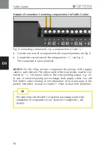
Page 74: ...e respective articles The present chapter gives you an outline of the vari ous possible connections Example of connection Connecting traffic lights and stop sections to the Traffic Light Control unit Fig 21 Connecting traffic lights and stop sections X X Connect the coloured wires of the traffic lights to the positions provided Red wire to RT yellow wire to GE green wire to GN see Fig 21 X X Conne...

Page 75: ...red order to positions L1 up to L8 see Fig 22 X X Connect the red wires of the warning lights to see Fig 22 The warning lights are now connected ADVICE Warning lights connected to positions L1 up to L8 will then flash in that order In the appendix to the present instruction manual you will find some examples illustrating different possible applications of the Traffic Light Control unit on your Car...

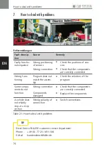
Page 76: ...c tioning Program does not match the assem bly X X Check the selection of the program Some compo nents do not function Wrong connection Components damaged X X Check that the components are correctly connected X X Replace the components A vehicle does not reliably stop at a stop section Wrong polarity of connection X X Switch connections Table 21 How to deal with problems Direct line to FALLER s cu...

Page 77: ...may not connect any source of current to any input of the Traffic Control ADVICE All inputs are potential free that is to say there must not be any voltage at such inputs To perform any activation only use sensors push buttons switches or switching tracks Outputs The outputs are protected from 650 mA onwards via three current limiting devices so that up to four components consuming each 150 mA may...

Page 78: ... most of the programs the duration for which an output of your Traffic Control or Traffic Light Control is activated The angle of rotation ranges between 0 bottom right and 270 top right Position 0 corresponds to the shortest adjustable duration of 1 second while 270 cor respond to the longest adjustable duration of 35 seconds Flip flop On a flip flop an output e g a stop section is activated thro...

Page 79: ...mm Secure the sensor within the bore using a drop of instant adhesive On doing so position the flat edge of the otherwise circular surface of the sensor at a right angle to the direction of drive Make sure that both ends of the guide wire run right up to the sensor ADVICE Avoid building any sensors into curves Additional magnets If a given component should not be activated by every vehicle sensors...

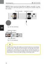
Page 80: ...dy FALLER Laser Street will enable you to build nearly any circuit design you may want The plug in street elements are available with ready cut groove for the contact wire fore bores to receive the sensors or branch off junctions as well as markings for the accurate positioning of stop sections It has never been so easy to build busy roads TIP Dry reed switch Dry reed switch Additional magnet Addi...

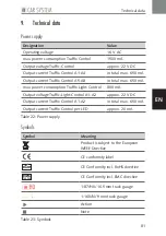
Page 81: ... max power consumption Traffic Light Control 800 mA Output voltage Traffic Light Control A1 A2 approx 22 V DC Output current Traffic Control A1 A2 in total max 650 mA Output current Traffic Control per LED approx 20 mA Table 22 Power supply Symbols Symbol Meaning Product is subject to the European WEEE Directive CE conformity label RoHS CE Conformity incl RoHS directive EMC tested CE Conformity in...

Page 82: ...82 Notizen Notes EN 11 Notizen Notes DE ...

Page 83: ...wing appendix merely repre sent a small selection of the possible traffic scenarios and are intended to help you implement your own design and layout You may want to copy these examples accurately or to complement them but also to combine them with one another so as to reproduce any conceivable traffic scenario on your model installation Just be creative For the sake of clearness the schematic dra...

Page 84: ...1 wird die Aktivierungsdauer der Stopp Stelle um die eingestellte Zeit verlängert Hierdurch werden Auf fahrunfälle vermieden X X Schließen Sie die Komponenten an siehe Abb 28 Scenario H0 Bus stop At a bus stop a vehicle is directed to the bus bay and stopped there Vehic les that follow meanwhile drive the straight lane Prerequisite condition Vehicles that have to enter the bus bay must be pro vide...

Page 85: ...85 Anhang Appendix EN DE SE 1 SE 2 FAHRTRICHTUNG ST 1 Fahrdraht Abzweigung Stopp Stelle Sensor Bushaltestelle H0 11 mm ca 2 mm 16 V 16 V 10 mm 80 mm 40 mm AB 1 Abb Fig 28 Bushaltestelle H0 H0 Bus stop ...

Page 86: ...opp Stelle um die eingestellte Zeit verlängert Hierdurch werden Auf fahrunfälle vermieden X X Schließen Sie die Komponenten an siehe Abb 29 Scenario N Bus stop At a bus stop a vehicle is directed to the bus bay and stopped there Vehic les that follow meanwhile drive the straight lane Prerequisite condition Vehicles that have to stop in the bus bay must be provided with an additional out of line ma...

Page 87: ...87 Anhang Appendix EN DE ST 1 SE 1 FAHRTRICHTUNG Bushaltestelle N 16 V 16 V Fahrdraht Abzweigung Stopp Stelle Sensor ca 2 mm 11 mm 30 mm 6 mm SE 2 AB 1 6 mm Abb Fig 29 Bushaltestelle N N Bus stop ...

Page 88: ...rive onto the opposite lane If a vehicle drives over sensor SE1 stop section ST1 will be activated for an adjustable period of time If an oncoming vehicle drives over the stop sec tion ST1 during that time it will be stopped X X Connect the components see Fig 30 ADVICE During the installation observe the spacing required between com ponents and sensors Please visit us at www faller de to get an en...

Page 89: ...89 Anhang Appendix EN DE ST 1 SE 1 FAHRZEUG 2 FAHRZEUG 1 ENGSTELLE Engstelle Baustelle x 1 5 x 16 V Fahrdraht Stopp Stelle Sensor 11 mm Abb Fig 30 Engstelle Baustelle Bottleneck Construction site ...

Page 90: ...ahrzeug die Stopp Stelle ST1 während dieser Zeit wird es angehalten X X Schließen Sie die Komponenten an siehe Abb 31 Scenario Distance control The distance control is intended to ensure that there is sufficient space bet ween two vehicles ADVICE Depending on the program selected the stop section will be acti vated for a preset period of time or for an adjustable time Poti If a vehicle drives over...

Page 91: ...91 Anhang Appendix EN DE SE 1 ST 1 FAHRTRICHTUNG Abstandssteuerung 16 V Fahrdraht Sensor Stopp Stelle 11 mm min 100 mm Abb Fig 31 Abstandssteuerung Distance control ...

Page 92: ...opp Stelle ST1 für eine bestimmte Zeit aktiviert und das Fahrzeug hält an X X Schließen Sie die Komponenten an siehe Abb 32 Scenario A vehicle stops by itself All vehicles are stopped on grounds of an arbitrary situation e g in front of a zebra crossing ADVICE Depending on the program selected the stop section will be acti vated for a preset period of time or for an adjustable time Poti If a vehic...

Page 93: ...93 Anhang Appendix EN DE FAHRTRICHTUNG Fahrzeug hält sich selbst an ST 1 16 V 11 mm Fahrdraht Sensor Stopp Stelle SE 1 Abb Fig 32 Ein Fahrzeug hält sich selbst an A vehicle stops by itself ...

Page 94: ...ungen AB1 AB2 können wieder aktiviert werden X X Schließen Sie die Komponenten an siehe Abb 33 Scenario Diagonal parking spaces ADVICE The examples stated in square brackets are taken from program 8 see chapter Traffic Control programs If a vehicle drives over sensor SE1 at E1 branch off junction AB1 at A1 will be activated The vehicle turns into the first bay to parking space P1 at A2 and stops A...

Page 95: ...95 Anhang Appendix EN DE SE 1 SE 2 P 1 P 2 FAHRTRICHTUNG AB 1 AB 2 Fahrdraht Abzweigung Sensor Parkplatz Freigabetaster Parkharfe 16 V T 1 T 2 T x 14 mm Abb Fig 33 Parkharfe Diagonal parking spaces ...

Page 96: ...nden Car System Anlagen finden Sie in unserer Broschüre Modellbau leicht gemacht FALLER Car System Art 190847 TIPP Scenario Right of way When controlling roadway traffic at crossroads and junctions the priority rule has to be applied Any vehicle coming from the right has the right of way while other vehicles coming from the left must wait ADVICE Depending on the program selected the stop section w...

Page 97: ...97 Anhang Appendix EN DE ST 1 SE 1 ST 2 SE 2 FAHRZEUG 3 FAHRZEUG 1 FAHRZEUG 2 Rechts vor links 16 V Fahrdraht Sensor Stopp Stelle 11 mm Abb Fig 34 Rechts vor links Right of way ...

Page 98: ...er Freiga betaster an E2 bzw an E4 einheitlich 2 Sekunden Scenario Speed measurement Advice The examples stated in square brackets are taken from program 10 see chapter Traffic Control programs If a vehicle when driving from sensor SE1 at E1 to sensor SE2 at E3 requires a longer period of time than the duration set at the potentiometer branch off junction AB1 at A1 will be activated for 2 seconds ...

Page 99: ... SE 1 SE 2 P 1 P 2 FAHRTRICHTUNG AB 1 AB 2 Fahrdraht Abzweigung Sensor Parkplatz Freigabetaster Geschwindigkeitsmessung 16 V T 1 T 2 T x 14 mm ca 200 mm 20 mm ca 70 mm Abb Fig 35 Geschwindigkeitsmessung Speed measurement DE ...

Page 100: ...2 und ST3 erst mit einer über Poti 1 einstellbaren Verzögerung freigegeben um einen Abstand zwi schen den Fahrzeugen zu gewährleisten Scenario Unprotected level crossing Advice The examples stated in square brackets are taken from program 15 see chapter Traffic Control programs The passage of a train over train s contact beginning at E3 activates one or two main stop sections HST at A3 as well as ...

Page 101: ...t Ende FAHRTRICHTUNG Fahrdraht Andreaskreuz Stopp Stelle FAHRTRICHTUNG ZUG Art Nr 161657 ST 2 SE 1 HST BL 1 ST 3 SE 2 HST BL 2 18 5 mm 40 mm 70 mm 173 mm 150 mm 150 mm 1 5 mm 3 mm 10 mm SE 2 Sensor 16 V 11 mm FAHRTRICHTUNG Abb Fig 36 Unbeschrankter Bahnübergang Unprotected level crossing DE ...

Page 102: ...WEIS Sie können zusätzlich am Lauflicht Anschluss der Traffic Light Control LED Warnbaken Art 161830 anschließen siehe Abb 37 Scenario Bottleneck with traffic lights ADVICE Two traffic lights at most can be connected to one port Traffic lights connected to outputs Ampel 1 and Ampel 2 operate alter nately contrary course Whenever one of both traffic lights is in the Yellow phase the stop section in...

Page 103: ... Anhang Appendix EN DE FAHRZEUG 2 FAHRZEUG 1 ENGSTELLE Engstelle mit Ampeln Ampel Licht ST 1 ST 2 16 V 11 mm 1 2 11 mm Fahrdraht Stopp Stelle Abb Fig 37 Engstelle mit Ampeln Bottleneck with traffic lights ...

Page 104: ... Ampel 1 am Poti 1 siehe Tab 4 Potentiometer Poti Die Ampeln sind angeschlossen und eingestellt Scenario Pedestrian crossing with traffic lights ADVICE Two traffic lights at most can be connected to one port The traffic lights operate simultaneously Whenever the traffic lights are in the Yellow phase both stop sections are activated and the vehicles are stopped As soon as the traffic lights switch...

Page 105: ...05 Anhang Appendix EN DE FAHRZEUG 1 FAHRZEUG 2 Fußgängerüberweg mit Ampeln Ampel ST 1 ST 2 16 V Fahrdraht Stopp Stelle 11 mm 11 mm 1 1 Abb Fig 38 Fußgängerüberweg mit Ampeln Ped crossing w traffic lights ...

Page 106: ... Poti 2 siehe Tab 4 Potentiometer Poti Die Ampeln sind angeschlossen und eingestellt Scenario Traffic crossroads with traffic lights ADVICE Two traffic lights at most can be connected to one port The traffic lights operate alternately contrary course Whenever the traf fic lights on the main road switch to Yellow the stop sections on the main road are activated and the vehicles are stopped During t...

Page 107: ...nhang Appendix EN DE FAHRTRICHTUNG ST 1 ST 2 ST 3 16 V Ampelkreuzung Ampel Fahrdraht Stopp Stelle 11 mm 11 mm 11 mm FAHRTRICHTUNG 2 2 1 Abb Fig 39 Verkehrskreuzung mit Ampeln Traffic crossr w traffic lights ...

Page 108: ...108 Notizen Notes EN DE 12 Notizen Notes ...

Page 109: ...109 Notizen Notes EN DE 13 Notizen Notes ...

Page 110: ...110 Notizen Notes EN 14 Notizen Notes DE ...

Page 111: ...111 Notizen Notes EN 15 Notizen Notes DE ...

Page 112: ...erungen vorbehalten Subject to modifications 24 03 2017 Gebr FALLER GmbH Kreuzstraße 9 D 78148 Gütenbach Telefon 49 0 77 23 651 0 Telefax 49 0 77 23 651 123 www faller de info faller de The German instruction manual is the original version ...

Reviews: