background image

APPENDIX A

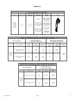
Table 1A: Specifications for 

FT-X Web SRL-P

Model #

Lifeline Material

Working Length 

and Weight

Materials and 

Specifications

Capacity and 

Standards

Images

84711SA1

84711SA3

84711SA4

84711SC1

84711SC3

84711SG4

Dyneema

11 ft. (3.4 m)

3.5 lbs. (1.6 kg)

Housing:

Nylon

Anchorage Carabiner:

5,000 lbs (22.2 kN)

with 3,600 lbs (16 kN) 

Gate Strength

Leg-end Connectors:

5,000 lbs (22.2 kN)

with 3,600 lbs (16 kN)

Gate Strength

Single User Capacity 

for ANSI Compliance:

130 to 310 lbs.

(59 to 141 kg)

Single User Capacity 

for OSHA Compliance:

130 to 420 lbs.

(59 to 191 kg)

ANSI Z359.14-2021

Class 1

OSHA 1926.502

OSHA 1910.66

102022

MSRD26 Rev B

17

Table 1B: 11' FT-X Web Performance for 130 to 310 lbs. (59 to 141 kg) User

Part #s and Conditions

Typical Performance for 

130 to 310 lbs. (59-141 kg) User

ANSI Performance Requirements

130 to 310 lbs. (59-141 kg) User

Part #

Anchorage Condition

Arrest 

Distance

Average 

Arrest Force

Maximum Arrest 

Force

Maximum 

Arrest 

Distance

Average 

Arrest Force

*Conditioned

Maximum Arrest 

Force

All part num-

bers shown 

in Table 1A 

above

Overhead, Non-Leading Edge

(ANSI Z359.14-2021)

32”

(0.8 m)

936 lbf

(4.2 kN)

1,333 lbf

( kN)

42”

(1.1 m)

1,575 lbf

(7.0 kN)

1,800 lbf

(8 kN)

5' Below D-Ring, Non-Leading 

Edge (OSHA)

81”

(3.1 m)

933 lbf

(4.2 kN)

1,235 lbf

(5.5 kN)

N/A

N/A

Table 1C: 11' FT-X Web Performance for 311 to 420 lbs. (141 to 191 kg) User

Part #s and Conditions

Typical Performance for 

311 to 420 lbs. (141-191 kg) User

Part #

Anchorage Condition

Arrest 

Distance

Average 

Arrest Force

Maximum Arrest 

Force

All part num-

bers shown 

in Table 1A 

above

Overhead, Non-Leading Edge

40”

(1.0 m)

756 lbf

(3.3 kN)

1,110 lbf

(4.9 kN)

3' Below D-Ring, Non-Leading 

Edge

85”

(2.2 m)

884 lbf

(3.9 kN)

1,375 lbf

(6.1 kN)

Summary of Contents for 11' FT-X Web Class 1 SRL-P

Page 1: ...tructions as required by the American National Standards Institute ANSI Z359 and should be used as part of an employee training program as required by the Occupational Safety and Health Administration...

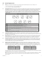
Page 2: ...6 7 8 13 13 15 16 18 For purposes of this manual the 11 FT X Web Class 1 Self retracting Lifeline in all iterations may be referred to collectively as the 11 FT X Web the FT X Web the SRL P the FT X t...

Page 3: ...pacity limits Heavy users experience more risk of serious injury or death due to falls because of increased fall arrest forces placed on the user s body In addition the onset of suspension trauma afte...

Page 4: ...eight up to 310 lbs or at a maximum of 3 below the user s FBH dorsal D ring for a worker weighing 311 to 420 lbs Below D ring tie off is outside the scope of ANSI Z359 and is only allowed when no edge...

Page 5: ...user instruction manual for how to calculate your Minimum Required Fall Clearance MRFC using the affixed labels Classification information found on product labels is based on test results Table 1B in...

Page 6: ...f the three principal parameters Arrest Distance Average Arrest Force and Maximum Arrest Force listed by model number and class Testing is conducted under various environmental conditions at ambient t...

Page 7: ...pplication must have the strength to sustain a static load applied in the direction permitted by the PFAS of at least a Two times the maximum arrest force permitted when certification exists or b 5 00...

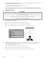
Page 8: ...nce with Section 7 Remove the device from service if the inspection shows damage or any malfunction Don the FBH and or attach the SRL in accordance with the harness manufacturer s instructions Follow...

Page 9: ...RD Do not use the SRD if inspection shows damage or any malfunction Don the FBH in accordance with the FBH manufacturer s instructions Follow the instructions contained in this manual and on the label...

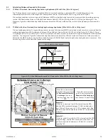
Page 10: ...he walking working surface SRD Deceleration Distance D Ring Shift and Harness Stretch 1 ft 0 3m Safety Factor 1 5 ft 0 5m and Swing Fall The diagram in Figure 6 is calculated using the performance dat...

Page 11: ...ed from the walking working surface SRD Deceleration Distance D Ring Shift and Harness Stretch 1 ft 0 3m Safety Factor 1 5 ft 0 5m and Swing Fall The diagram in Figure 8 is calculated using the perfor...

Page 12: ...detergent water solution Do not allow water or other corrosion causing elements to enter the housing After cleaning pull the lifeline all the way out allow the unit to air dry then retract the lifelin...

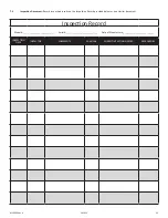
Page 13: ...provided below or on a similar document Inspection Record Model _________________________ Serial _________________________ Date of Manufacture _________________________ INSPECTION DATE INSPECTOR COMM...

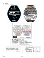
Page 14: ...8 0 Labels The labels must be present and legible 102022 MSRD26 Rev B 14...

Page 15: ...fall protection program who through training and knowledge is capable of identifying evaluating and addressing existing and potential fall hazards and who has the employer s authority to take prompt c...

Page 16: ...sitioning The act of supporting the body with a positioning system for the purpose of working with hands free Positioning Lanyard A lanyard used to transfer forces from a body support to an anchorage...

Page 17: ...rformance for 130 to 310 lbs 59 141 kg User ANSI Performance Requirements 130 to 310 lbs 59 141 kg User Part Anchorage Condition Arrest Distance Average Arrest Force Maximum Arrest Force Maximum Arres...

Reviews: