


Rev A
110826
MSRD45.1
TABLE OF CONTENTS
1. DESCRIPTION
1.1 ANSI and OSHA
2. PRODUCT ASSEMBLY AND OPERATION
3. SPECIFICATIONS
3.1 Capacity
3.2 Compatibility of Connectors
3.3 Compatibility of Components
3.4 Making Connections
3.5 Personal Fall Arrest System
3.5.1 Average Arrest Force and Arrest Distance
3.6 Personal Fall Arrest System Anchorage Strength
4. MAINTENANCE, SERVICE AND STORAGE
4.1 Maintenance
4.2 Service
4.3 Storage
5. INSPECTION
5.1 Pre-Use Inspection:
5.2 Inspection Frequency:
5.3 Inspection Checklist:
5.4 Inspection Results:
5.5 Inspection Document
6. LABELS AND MARKINGS
APPENDIX A
Specific Tables and Figures TBD
1. DESCRIPTION
This manual is a supplement/addendum to Section 4.5.1, 4.5.2 and 4.5.3 of FallTech user instruction manual MSRD07. The Locking Slide Bolt
SRD/FBH Connector for Single/Twin 6’ Mini SRDs is a forged, yellow-chromate zinc plated steel, triple action, dual locking connector for attaching
either single or twin Mini SRDs to a Full Body Harness (FBH). The Locking Slide Bolt SRD/FBH Connector described in this manual is designed to be
an alternative connector for attaching the FallTech Mini SRD to the user’s Full Body Harness. Prior to use of the connector described in this
manual, the user must read and understand the contents of MSRD07 “DuraTech Mini 6’ Single/Twin Self-Retracting Device.”
1.1
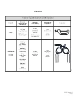
ANSI and OSHA Regulations: The Locking Slide Bolt SRD Connector described in this manual when used as instructed in this manual is ANSI
Z359.12 and OSHA compliant. See Table 1A and Figure 1 for complete component specifications and system description.
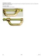
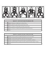
2. PRODUCT ASSEMBLY, INSTALLATION AND OPERATION
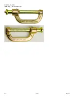
To install the connector:
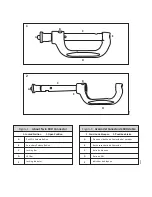
1.
Depress both release buttons and slide the locking bar into the open position as shown in Figure 1.
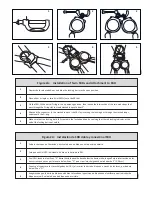
2.
Place either a single or twin Mini SRD(s) onto the SRL bar as shown in Figure 2A.
3.
On the FBH, lift the dorsal D-ring to the up-pointing position, then loosen the intersection of the two web straps that pass through the D-
ring slot to create slacked loops of about 2” as shown in Figure 2A.
4.
Attach the connector to the slacked loops by inserting the locking bar through the slacked loops as shown in Figure 2A.
5.
Make sure the locking bar is in the fully inserted and locked position by verifying that the red locking indicator at the end of the locking
bar is not visible. See Figure 2B for correct and incorrect connector attachment.
3. SPECIFICATIONS: See Table 1A
4. MAINTENANCE, SERVICE AND STORAGE
Wipe with a soft cloth. Remove an excessive buildup of contaminants such as paint, grease, debris of any type that might impede the smooth
operation of the hinge and lock mechanism. When not in service, store in a clean, dry area. Do not store other equipment on top of the connector,
do not store in a manner that may result in damage from deformation forces or heat, corrosion, chemical or electric arcing.
5. INSPECTION
1.
Inspect for missing or altered parts.
2.
Inspect the entire Connector for any cracks, nicks or breaks in the metal.
3.
Inspect every inch of the Connector. Clean if necessary before inspection in order to detect small, hairline cracks.
4.
Inspect the Connector for deformation. Look for bent or dented parts. Open the gate and inspect the nose of the Connector for signs of wear,
distortion or breaks.
5.
Inspect the Connector surface for signs of corrosion. On steel Connectors, red dust is evidence of corrosion of the basis metal. Corrosion of
aluminum Connectors is evident by pitting or scale.
6.
Inspect markings. Markings should be present and fully legible.
7.
Inspect the Connector function to ensure the lock rotates and opens easily, closes and locks completely.
8.
Record the Connector inspection results in the Inspection Records, found in the appendix of this manual.
9.
If inspection reveals a defective condition, remove the unit from service. If the Connector has been subjected to fall arrest forces, remove it
from service.
5.4 Inspection Results:
5.5 Inspection Document: Record inspection results on the Inspection Record provided in Appendix B of MSRD07, or on a similar document.


