


12
7.
Before
use,
be
sure
to
inspect
in
accordance
with
the
instructions
in
section
8.2
of
this
manual.
Test
for
proper
braking
action
by
grasping
the
lifeline
and
pulling
down
hard,
ensuring
that
the
unit
locks.
8.
Attach
the
connector
on
the
attachment
end
of
the
SRL
to
the
back
D
‐
ring
of
your
Full
Body
Harness.
Ensure
that
the
connector’s
gate
is
closed
and
locked.
9.
You
are
now
attached
and
protected
by
the
SRL.
The
preferred
orientation
of
the
device
is
vertical
with
the
lifeline
exit
at
the
bottom;
however,
the
device
will
perform
either
completely
horizontal
or
any
other
angle.
To
assure
proper
lifeline
retraction,
keep
lifeline
path
clear
of
obstructions.
Beware
of
swing
fall
hazards
when
working
at
extreme
angles.
Once
the
above
steps
have
been
taken,
the
user
will
have
access
to
their
work
area
while
walking
and
moving
at
normal
speeds.
It
is
important
not
to
make
sudden
or
dramatic
movements,
as
the
SRL
is
designed
to
lock
up
when
the
line
begins
to
move
at
a
rate
of
4.5
feet
per
second.
Sudden
movements
or
acceleration
can
cause
the
SRL
to
lock
up,
which
may
“jerk”
the
user
and
could
result
in
the
user
losing
his
or
her
balance.
When
using
the
equipment,
care
must
be
taken
to
be
aware
of
the
work
environment
and
any
hazards,
obstructions
or
obstacles
that
may
exist.
Be
careful
of
any
and
all
fall
hazards
and
also
be
aware
of
slipping
and
tripping
hazards
as
well.
Section
4:
Product
Selection
Product
selection
is
as
important
as
the
proper
use
of
the
product
itself.
Poor
judgment
in
product
selection
can
have
catastrophic
results
–
therefore
be
sure
to
consult
a
competent
person
to
ensure
that
the
product
that
is
issued
is
appropriate
for
the
application
and
the
specific
location
for
which
it
is
intended.
ANSI
Z359.1
‐
2007,
Section
7
describes
in
detail
the
steps
that
should
be
taken
with
regard
to
the
selection
of
fall
arrest
equipment.
FallTech
strongly
encourages
the
use
of
this
guide
by
those
who
employ
users
of
fall
arrest
products.
The
ANSI
standard
recommends
the
following
steps
be
taken:
A
workplace
assessment
by
a
competent
person
taking
into
account
the
presence
of
sources
of
extreme
heat,
chemicals,
electrical
hazards,
environmental
contaminants,
sharp
objects,
abrasive
surfaces;
moving
equipment
and
materials,
unstable,
uneven
and
slippery
walking/working
surfaces;
unguarded
openings;
climatic/weather
factors
and
foreseeable
changes
to
these
conditions.
Care
must
be
taken
to
ensure
that
the
equipment
that
is
selected
is
suitable
for
use
where
any
of
these
conditions
may
exist.
The
workplace
assessment
must
identify
all
paths
of
movement
and
the
fall
hazards
along
these
paths.
Care
must
be
taken
to
ensure
that
there
are
proper
anchorages
at
appropriate
intervals
along
these
paths
to
protect
the
users
from
these
hazards
without
exposure
to
swing
‐
fall
conditions.
The
PFAS
selected
must
limit
the
fall
distance
in
order
to
avoid
contact
with
the
next
lower
level
in
the
event
of
a
fall.
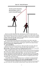
Anchorage
connectors
should
be
selected
on
the
basis
of
their
suitability
for
attachment
to
the
anchor
point
to
ensure
a
compatible
and
secure
connection.
The
exposure
of
the
anchorage
connector
to
sharp
edges,
abrasive
surfaces
and
other
physical/structural
hazards
should
be
considered
when
evaluating
compatibility.
The
competent
person
shall
calculate
the
weight
of
all
authorized
persons
when
fully
equipped
to
ensure
that
they
are
within
the
maximum
capacity
of
the
PFAS.
A
full
body
harness
meeting
the
requirements
of
Z359
shall
be
selected,
and
it
shall
be
sized
to
fit
the
user
as
per
the
manufacturer’s
instructions.
Connectors
that
are
selected
shall
be
suitably
sized
and
shaped
so
as
to
be
compatible
with
the
devices
to
which
they
will
be
attached.
The
competent
person
shall
select
the
method
of
protecting
the
equipment
from
damage
by
workplace
conditions,
in
accordance
with
the
manufacturer’s
instructions.
The
competent
person
shall
check
the
equipment
instructions
and
markings
to
ensure
compliance
with
the
appropriate
standards
and
will
ensure
that
manufacturer’s
instructions;
markings
and
warnings
are
read
and
followed.


