background image


7


harness


and


a


self

retracting


lifeline,


shock

absorbing


lanyard


or


other


deceleration


device


designed


to


bring


a


falling


user


to


a


stop


in


the


shortest


possible


distance


while


limiting


the


force


imparted


to


the


user’s


body.


2.6:


Fall


Restraint


Fall


Restraint


is


an


area


of


Fall


Protection


devoted


to


restraining


the


user


of


the


system


in


a


manner


which


restricts


his


or


her


access


to


the


fall


hazard


in


a


manner


such


that


they


cannot


be


subjected


to


a


fall.


A


typical


Fall


Restraint


System


consists


of


an


anchorage,


a


full


body


harness


or


a


restraint


belt


and


a


restraint


lanyard.


An


SRL


should


never


be


utilized


in


a


restraint


application


as


it


is


not


capable


of


restricting


a


user’s


access


to


fall


hazards.


2.7:


Work


Positioning


Work


Positioning


is


an


area


of


Fall


Protection


devoted


to


allowing


a


user


to


work


on


a


vertical


surface


by


means


of


a


positioning


assembly,


and


restricting


the


user’s


exposure


to


a


fall


of


no


more


than


two


feet.


Typical


positioning


assemblies


consist


of


a


large


rebar


hook


and


a


length


of


chain,


rope,


wire


rope


or


webbing


with


a


double


locking


snap


hook


on


either


end.


These


snap


hooks


are


attached


to


d

rings


on


the


hips


or


on


the


waist


of


the


user’s


full


body


harness,


with


the


rebar


hook


attached


to


the


structure


upon


which


the


user


is


working.


An


SRL


should


never


be


used


for


work


positioning,


nor


should


it


ever


be


attached


to


a


side


or


hip


d

ring


on


a


full


body


harness.


2.8:


Free

Fall


Free

Fall


is


the


distance


that


a


worker


will


fall


before


the


connecting


device


or


deceleration


device


elements


of


the


PFAS


will


begin


to


engage


during


a


fall


event.


OSHA


allows


a


maximum


Free

Fall


Distance


of


6’


(6


feet)


when


rigging


a


Personal


Fall


Arrest


System


(PFAS).


In


some


cases,


exceptions


may


be


allowed


when


there


is


no


practical


way


to


limit


the


Free

Fall


Distance


to


6’,


such


as


a


job

site


where


no


overhead


anchor

point


is


available.


Tying


off


in


a


manner


that


would


create


a


Free

Fall


greater


than


6’


should


always


be


a


last


resort.


If


you


are


rigging


a


system


that


allows


more


than


6’


of


Free

Fall,


make


sure


your


Connecting


Device/Deceleration


Device


is


rated


for


this


application.


FallTech


Web


SRL’s


ARE


NOT


rated


for


Free

Falls


greater


than


2’!


2.9:


Clear

Fall


Clear

Fall


or


Clear

Fall


Distance


is


the


distance


that


is


required


to


safely


arrest


the


fall


of


a


user.


When


working


at


heights


and


using


a


PFAS,


it


is


important


to


consider


the


distance


between


the


walking/working


level


and


the


next


lower


level


to


ensure


that


the


components


selected


are


capable


of


arresting


the


user’s


fall


before


they


hit


the


next


lower


level.


The


required


Clear

Fall


Distance


can


easily


be


calculated


by


adding


together


the


Free

Fall


Distance,


the


Deceleration


Distance,


the


height


of


the


user


plus


a


safety


factor


of


2


feet.


The


formula


for


calculating


Clear

Fall


Distance


is


shown


below:


Free

Fall


Distance


+


Deceleration


Distance


+


Height


of


Worker


+


Safety


Factor


=


Clear

Fall


Distance


The


matrix


below


can


be


used


as


a


guide


for


calculating


Clear

Fall


Distance


on


your


job

site:


Example


Values

Actual


Values

Free

Fall


Distance


(OSHA


allows


up


to


6’)

2’


Deceleration


Distance

(Typically


3.5’


or


less)

3.5’


Height


of


Worker


6’

Safety


Factor


(Minimum


of


2’)


2’


Total


(Sum


of


all


values)


13.5’


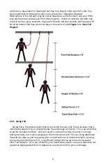
See


figure


2.1


on


the


next


page


for


a


graphic


illustration


of


Clear

Fall


Distance


and


the


method


for


calculating.


It


is


also


necessary


to


consider


the


fall


path


when


determining


the


Clear

Fall


limitations


in


your


application.


Ensure


the


fall


path


is


clear


of


obstructions,


Summary of Contents for 7262

Page 1: ...LURE TO UNDERSTAND AND COMPLY WITH THESE INSTRUCTIONS CAN RESULT IN SERIOUS INJURY OR DEATH IF THESE INSTRUCTIONS ARE UNCLEAR TO YOU PLEASE CONSULT A COMPETENT PERSON SHOULD THESE INSTRUCTIONS BECOME...

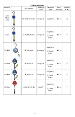
Page 2: ...Steel 310 lbs N 8262 8 Web Retractor Polyester Alloy Steel 3 600 lb Gates 310 lbs Y 7276WR 20 Web SRL Dyneema Alloy Steel 3 600 lb Gates 310 lbs Y 7271WR 15 Web SRL Polyester Alloy Steel 3 600 lb Gate...

Page 3: ...ons and Qualified Persons ANSI Z359 0 2007 goes on to further define the roles and qualifications of these individuals as well as Authorized Persons and their importance in the workplace These terms a...

Page 4: ...the line to retract SLOWLY back into housing Do make compatible connections see Advisory 3 at the end of this Section Do use a tagline if the SRL is remotely mounted to access cable and control the re...

Page 5: ...hat the rings or structural members to which they are attached will not pose a risk of forcing the gate open and must fully captivate the connector so that it cannot become disengaged slide or shift d...

Page 6: ...ched to a side or hip d ring Such a connection could cause serious injury or death Be sure to read and follow the manufacturer s instructions included with your full body harness at the time of purcha...

Page 7: ...ce of 6 6 feet when rigging a Personal Fall Arrest System PFAS In some cases exceptions may be allowed when there is no practical way to limit the Free Fall Distance to 6 such as a job site where no o...

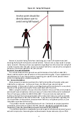
Page 8: ...iagram 2 10 Swing Fall Swing Fall is the phenomenon that occurs when the user falls from a location that is not directly adjacent to or directly below the anchorage connector This is also referred to...

Page 9: ...y out and retract automatically In the event of a fall a centrifugal brake will arrest the fall in a very short distance while greatly reducing the forces associated with the arrest Before using this...

Page 10: ...bove the walking working surface and allows for a maximum Free Fall Distance of 2 feet Horizontal Lifelines This product is suitable for use in any application where a horizontal lifeline has been ins...

Page 11: ...re proper deceleration in the event of a fall 2 Read understand and comply with manufacturer s instructions for each component of your Personal Fall Arrest System Full Body Harness Anchorage Connector...

Page 12: ...rs of fall arrest products The ANSI standard recommends the following steps be taken A workplace assessment by a competent person taking into account the presence of sources of extreme heat chemicals...

Page 13: ...e absence of certification If multiple personal fall arrest systems are being attached to the same anchorage the minimum values stated above must be multiplied by the number of users Ensure that the a...

Page 14: ...ilities of designated persons Authorized Competent Qualified How to use written fall protection procedures Inspection of equipment components and systems before use Fall protection rescue procedures I...

Page 15: ...s This condition can result in a variety of symptoms some of which include light headedness loss of consciousness difficulty concentrating and palpitations Following a rescue Suspension Trauma can be...

Page 16: ...urring If these conditions exist and are beginning to cause damage to the webbing remove the SRL from service 6 Inspect the carabiner snap hook gates at the anchorage and attachment ends of the produc...

Page 17: ...Use a damp rag to clean the surfaces of any connecting hardware 4 If there is an excessive build up of paint oil dirt tar or other contaminants that cannot be removed remove the SRL from service and...

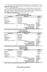
Page 18: ...Steel 5 000 lbs Overall static strength 3 000 lbs Arrest Forces 900 lbs Deceleration Distance 24 Maximum Capacity 310 lbs When tested in accordance with ANSI Z359 1 2007 FallTech Web SRL s Model s 727...

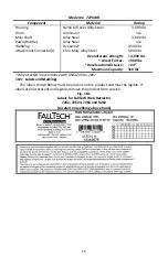
Page 19: ...teel 5 000 lbs Overall static strength 3 000 lbs Arrest Forces 900 lbs Deceleration Distance 24 Maximum Capacity 310 lbs When tested in accordance with ANSI Z359 1 2007 10 3 Labels and Markings The la...

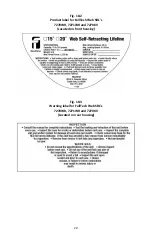
Page 20: ...20 Fig 10 2 Product label for FallTech Web SRL s 7270WR 7271WR and 7270KV Located on front housing Fig 10 3 Warning label for FallTech Web SRL s 7270WR 7271WR and 7270KV Located on rear housing...

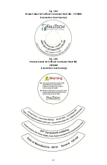
Page 21: ...21 Fig 10 4 Product label for FallTech Contractor Web SRL 7276WR Located on front housing Fig 10 5 Product labels for FallTech Contractor Web SRL 7276WR Located on rear housing...

Page 22: ...heck with your State Department of Labor for further details ANSI standards are available for purchase through the e standards store at www ansi org ANSI Z359 1 2007 Safety Requirements for Personal F...

Page 23: ...L ES PARTE ESTE PRODUCTO NO COMPRENDER NI CUMPLIR CON ESTAS INSTRUCCIONES PUEDE OCASIONAR LESIONES GRAVES O LA MUERTE SI ESTAS INSTRUCCIONES NO EST N CLARAS PARA USTED CONSULTE A UNA PERSONA COMPETENT...

Page 24: ...0 libras 1 633 kg Compuertas 310 libras 140 6 kg Y 7276WR SRL de red de 20 pies 6 1 m Dyneema Aleaci n de acero 3 600 libras 1 633 kg Compuertas 310 libras 140 6 kg Y 7271WR SRL de red de 15 pies 4 6...

Page 25: ...secci n para obtener m s detalles No utilizar componentes compatibles puede resultar en una falla del sistema para funcionar seg n lo previsto lo cual puede provocar lesiones graves o la muerte En los...

Page 26: ...los peligros del ca da con balanceo ver Secci n 2 9 S inspeccione toda la cuerda de salvamento de la SRL para detectar cortes abrasiones torceduras desgaste u otros da os S inspeccione el gancho con...

Page 27: ...Aviso No 1 Lectura adicional Si tiene acceso a Internet visite www osha gov Este sitio web es un recurso excepcional y tiene una gran cantidad de informaci n de f cil acceso Utilice el campo de b squ...

Page 28: ...nci n de ca das PFAS por sus siglas en ingl s La OSHA 1926 502 d 15 dispone lo siguiente Los anclajes utilizados para conectar los equipos personales de detenci n de ca das deber n ser independientes...

Page 29: ...n dispositivo de conexi n y de desaceleraci n pues lo mantendr conectado a su anclaje y reducir las fuerzas sobre su cuerpo en caso de una ca da Para obtener m s informaci n sobre la capacidad y las e...

Page 30: ...capaces de detener la ca da del usuario antes de que llegue al siguiente nivel inferior La distancia de ca da despejada requerida se puede calcular f cilmente al sumar la distancia de ca da libre la...

Page 31: ...e el usuario no s lo cae verticalmente sino que tambi n se balancea horizontalmente Esto puede ocasionar peligros adicionales por ejemplo puede balancearse hacia una obstrucci n o elemento estructural...

Page 32: ...etraer autom ticamente En el caso de una ca da un freno centr fugo detendr la ca da en una distancia muy corta mientras reduce en gran medida las fuerzas asociadas con la detenci n Antes de utilizar e...

Page 33: ...su sistema personal de detenci n de ca das lo cual puede resultar en lesiones graves o la muerte Aplicaciones directas por encima del nivel de la cabeza Este producto es apto para su uso en cualquier...

Page 34: ...n reas donde la cuerda de salvamento pueda entrar en contacto con temperaturas elevadas o escoria de soldadura FallTech recomienda el uso de la SRL con tramado de aramida Kevlar Nomex o Dyneema para e...

Page 35: ...s de ca das con balanceo cuando trabaje en ngulos extremos Una vez que se han tomado las medidas anteriores el usuario tendr acceso a su rea de trabajo mientras camina y se mueve a velocidades normale...

Page 36: ...egurar de leer y seguir las instrucciones marcas y advertencias del fabricante Si el PFAS que se selecciona posee componentes de diferentes fabricantes la persona competente se asegurar de que estos c...

Page 37: ...del producto equipos Si est obligado a proporcionar equipos de protecci n contra ca das para sus empleados aseg rese de consultar o nombrar a una persona competente o calificada para seleccionar y pre...

Page 38: ...ir barandillas redes cubiertas etc Los productos de detenci n de ca das son la ltima l nea de defensa en la jerarqu a de protecci n contra ca das y deben utilizarse como ltimo recurso por parte de los...

Page 39: ...sta afecci n puede resultar en una variedad de s ntomas entre los cuales se incluyen mareo p rdida de la conciencia dificultad para concentrarse y palpitaciones Despu s de un rescate el trauma por sus...

Page 40: ...te excesivo bordes cortantes o rebabas Si existen estas condiciones y est n empezando a da ar la cuerda retire la SRL de servicio 6 Inspeccione las compuertas del mosquet n gancho de conexi n en el an...

Page 41: ...es Aseg rese de que las etiquetas son legibles en todo momento 2 Utilice un trapo h medo y jab n suave y agua para limpiar la red de la SRL D jela secar 3 Utilice un trapo h medo para limpiar las supe...

Page 42: ...lificaci n Cubierta Aleaci n de acero 3 600 libras 1 633 kg Tambor Pl stico ABS n a Eje principal Aleaci n de acero 3 400 libras 1 542 2 kg Trinquetes Aleaci n de acero n a Red Poli ster 5 000 libras...

Page 43: ...iles SRL con red de la serie Contractor de FallTech No de modelo 7276WR Componente Material Calificaci n Cubierta Nil n 6 6 en aleaci n de acero 3 000 libras 1 360 8 kg Tambor Aluminio n a Eje princip...

Page 44: ...s para el Retractor de red de FallTech 7262 72624 7263 y 8262 Situadas en la cuerda encima del gancho Fig 10 2 Etiqueta del producto para las SRL de red de FallTech 7270WR 7271WR y 7270KV Situada en l...

Page 45: ...270KV Situada en la cubierta trasera Fig 10 4 Etiqueta del producto para la SRL de red de la serie Contractor de FallTech 7276WR Situada en la cubierta delantera Fig 10 5 Etiquetas del producto para l...

Page 46: ...tener protecci n contra ca das 1926 502 Criterios y pr cticas de los sistemas de protecci n contra ca das 1926 503 Requisitos de capacitaci n Las normas ANSI son est ndares de consenso voluntario y so...

Page 47: ...______________________ ________________________________________ ________________________________________ ________________________________________ ________________________________________ _____________...

Page 48: ...garant a no es transferible Ninguna otra persona o empresa est autorizada para asumir o ceder a FallTech cualquier otra garant a en relaci n con la venta o uso de este producto Asimismo esta garant a...

Reviews: