background image

Drill a ¾ in. hole. Clear away any debris. Push the Toggle Bar into the insert position. 
Insert the Toggle Bar into the hole and push the loop until the spring reaches full 
compression. Hold the hole plug in place and allow the spring to fully expand. The 
Toggle Bar will rotate into the deployed position. Tug firmly on the loop to ensure the 
Toggle Bar is deployed. 

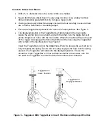
Ensure the axis of the Toggle Bar is parallel to the I-beam’s center web axis. Refer back 
to Figure 4. The ToggleLok is ready to use. 

NOTE: 

  Never rely on a unit placed by unqualified workers. 

  Remove the ToggleLok  at the end of each day. 

  Never leave a unit inserted in a hole overnight. 

  Inspect the unit for damage each time you use it. If damage has occurred, 

dispose of unit. 

INSTALLATION INSPECTION 

Once installation of the ToggleLok anchor is complete, ensure the following before use:  

  the permanent label is affixed to unit 

  cable is not kinked, frayed or damaged 

  metal components are not damaged 

IMPORTANT 

If a previously drilled hole is to be used, inspect it carefully and ensure it is of the correct 
size and location. 

Ensure the Toggle Bar is activated in the deployed position before placing a load on the 
anchor.  

The ToggleLok is designed to flex under impact loads. Do not allow any object to fall 
onto the ToggleLok. Do not allow the Anchor Loop or the Main Cable to become kinked 
or deformed..  

REMOVE THE TOGGLELOK 

Grasp the plug in one hand. With the other hand, push the loop toward the plug to fully 
compress the spring.  Draw the ToggleLok from the mounting hole. 


STORAGE AND CLEANING 

  Remove debris with compressed air. 

  Store in a clean, dry place. 

  At the end of every work day, remove from installation. 

Summary of Contents for 7442

Page 1: ...peration Instruction Manual Toggle Lok Anchor Model 7442 Portable Concrete Anchorage Connector ANSI Z359 1 5 000 lbs 22 24 kN FallTech Inc 1306 Alameda Street Compton CA 90221 800 719 4619 323 752 006...

Page 2: ...losed and locked Connector strength must meet the 5 000 lb requirements All personal fall arrest systems must meet all applicable state federal city OSHA and ANSI requirements and any other regulating...

Page 3: ...ial The Toggle Lok anchor may be mounted on horizontal surfaces vertical surfaces and overhead ceiling surfaces If a previously drilled hole is to be used inspect it carefully and ensure it is of the...

Page 4: ...num Trigger Assembly Capacity 130 400 lbs 59 181 kg Lot 120814 Make only compatible connections Avoid contact with harsh chemicals excessive heat and high voltage Do not use in wet or uncured concrete...

Page 5: ...Copper Return Wire 1x19 Aircraft Cable INSTALLATION LOCATION Choose the mounting location carefully Free fall distance shall be limited to 6 feet Always calculate the fall distance and ensure that a c...

Page 6: ...The unit is straight and operates smoothly The label is affixed to the unit The cable is not kinked frayed or damaged The metal components are not damaged The Toggle Bar operates freely MOUNT THE TOG...

Page 7: ...so it points straight out in line with the main cable When the machined flat on the end of the toggle bar engages the flat on the bottom of the hole plug the Toggle Bar with remain in the insert posi...

Page 8: ...n ensure the center of the drilled hole is at least 1 in from the edge of the beam See Figure 4 for acceptable mounting orientations Do not exceed 90 degree bends Figure 5 depicts an unacceptable orie...

Page 9: ...INSTALLATION INSPECTION Once installation of the ToggleLok anchor is complete ensure the following before use the permanent label is affixed to unit cable is not kinked frayed or damaged metal compone...

Page 10: ...ce it where it can be stepped on Keep the unit free of grease dirt and oil Do not lend the unit to others DISPOSAL If a fall arrest event has occurred or if inspection has revealed a fault or unsafe c...

Reviews: