background image


User Instruction Manual 


Rail Anchor 


This manual is intended to meet the Manufacturer's Instructions as required by ANSI Z359 and should be used as part of an 
employee training program as required by OSHA. This manual assumes the user has received training in the use of this 
equipment. 


WARNING 

This product is part of a personal fall arrest, restraint, work positioning, suspension, or rescue system. A Personal Fall Arrest 
System (PFAS) is typically composed of an anchorage and a Full Body Harness (FBH), with a connecting device, i.e., a Shock 
Absorbing Lanyard (SAL), or a Self-Retracting Device (SRD), attached to the dorsal D-ring of the FBH. 


Provide these instructions to the user of this equipment. The user must read and understand the manufacturer's 
instructions for each component or part of the complete system. Follow manufacturer's instructions for proper use, care, 
and maintenance of this product. Retain these instructions and keep them available for the user’s reference at all times. 
Alterations or misuse of this product, or failure to follow instructions, may result in serious injury or death. 


A Fall Protection Plan must be on file and available for review by all users. It is the responsibility of the user and the 
purchaser of this equipment to assure that users of this equipment are properly trained in its use, maintenance, and 
storage. 


Training must be repeated at regular intervals. Training must not subject the trainee to fall hazards. 
When this equipment is in use the employer must have a rescue plan and the means at hand to implement it and 
communicate that plan to users, authorized persons, and rescuers. 


Consult a doctor if there is reason to doubt your fitness to safely absorb the shock of a fall event. Age and fitness seriously 
affect a worker’s ability to withstand falls.  Pregnant women or minors must not use this equipment. 

NOTE: 

For more information consult ANSI Z359 


1306 South Alameda Street 

Compton, CA 90221, USA 

1-800-719-4619 
1-323-752-0066 

www.falltech.com


©2014 


MANC11ALX Rev A  

060414

Summary of Contents for 7495A

Page 1: ...se instructions and keep them available for the user s reference at all times Alterations or misuse of this product or failure to follow instructions may result in serious injury or death A Fall Prote...

Page 2: ...y Harness FBH and a deceleration device The anchor may only be used to traverse the rail with an 12 foot free fall lanyard that is compliant with ANSI Z359 13 2013 FallTech part number 8248 The Rail A...

Page 3: ...selected for PFAS must be able to sustain a static load applied in the direction permitted by the PFAS of at least...

Page 4: ...stance for the PFAS to function in case of a fall event The Fall Clearance Distance can be calculated in many different ways depending on equipment Attaching to a foot level anchor increases fall clea...

Page 5: ...of the railhead when in use 7 2 Annual Inspection by a Competent Person An annual inspection by a competent person is required See Figure 8 In addition to the steps in paragraph 7 1 perform the follow...

Page 6: ...to correctos de este producto Conserve estas instrucciones y mant ngalas disponibles para consulta del usuario en todo momento Las alteraciones o el uso indebido de este producto o no seguir las instr...

Page 7: ...ocado en un riel de ferrocarril horizontal con una pendiente m xima del 15 El Anclaje para riel se puede utilizar como un anclaje deslizante para facilitar el paso a lo largo de la v a f rrea para la...

Page 8: ...la autorizaci n para tomar con prontitud medidas correctivas para eliminarlos Persona calificada Una persona con un t tulo o certificado profesional reconocido y con amplios conocimientos capacitaci...

Page 9: ...anclaje con una soluci n de jab n y agua Seque con un pa o Almacene en interiores Evite los vapores qu micos la humedad y los da os f sicos 7 PROCEDIMIENTO DE INSPECCI N El usuario debe inspeccionar e...

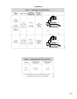
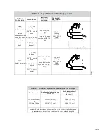
Page 10: ...0 lbs Zinc Plated 1 4 Steel 310 lbs ANSI Z359 1 OSHA 1926 502 5k gate Connector 7495A 7 long 3 3 4 wide 5 000 lbs 310 lbs ANSI Z359 1 Rail Anchor 6 1 4 tall 2 1 2 eye Zinc Plated 1 4 Steel OSHA 1926 5...

Page 11: ...502 pestillo 2 1 2 6 4 cm de 5k de ojal 7 17 8 cm de largo 7495A Anclaje para riel 3 3 4 9 5 cm de ancho 6 1 4 15 8 cm de alto 5 000 libras 2 268 kg Acero de aleaci n cincado de 1 4 0 6 cm 310 libras...

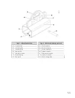
Page 12: ...C Interlocking Tab D Securing Hole E Side Plate of Anchor F Anchor Opening G Securing Pin Fig 1 Acerca del Anclaje para riel A Ojal de conector B Ranura de bloqueo C Pesta a de bloqueo D Agujero de fi...

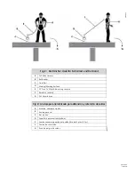
Page 13: ...ree Fall Shock Absorbing Lanyard F Restraint Lanyard G Fall Hazard Area Fig 2 Anclaje para riel utilizado para detenci n y retenci n de ca das A Arn s de cuerpo completo B Anclaje para riel C Riel de...

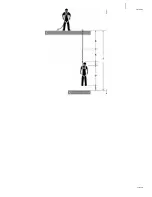
Page 14: ...r Level or Obstruction Fig 3 Requisito m nimo de ca da despejada Cuerda para ca da libre de 12 pies Medida desde el conector de anclaje superior A 6 pies 1 8 m Longitud de la cuerda con amortiguaci n...

Page 15: ...06132014 1 Superficie para caminar trabajar 2 Nivel inferior m s cercano u obstrucci n APPENDIX A DUCF2 1 TUCF2 2...

Page 16: ...il Anchor D 12 Free Fall Shock Absorbing Lanyard E Impact Hazard After Fall Fig 4 Ca da con balanceo con amarre al nivel de los pies A Superficie para caminar trabajar B Riel de tren C Anclaje para ri...

Page 17: ...easurement is always taken at bottom of Rail Head as indicated Fig 5 Ancho del cabezal del riel para usar con el anclaje A Cabezal del riel B Medici n del punto de anchura C Correa de riel D Pie de ri...

Page 18: ...rections D Insert Securing Pin in Hole E Attach 5k Gate Carabiner of SAL Fig 6 Instalaci n del anclaje para riel A Colocar las dos placas laterales en el riel B Insertar la pesta a en cada lado en la...

Page 19: ...DO NOT use with SRD as Fall Arrest Option B DO NOT use Standard Connectors 5k Gate Only C NOT for use on Head free Rail Fig 7 Uso incorrecto del anclaje para riel A NO utilizar con SRD como una opci...

Page 20: ...lways Below Bottom Edge of Rail Head C Minimum Side Plate Thickness 3 16 Fig 8 Inspecci n de degradaci n del anclaje A Ancho m ximo de la apertura del anclaje 1 1 2 3 8 cm B La punta del anclaje siemp...

Page 21: ...nclaje y por lo tanto producir un riesgo adicional de conexi n falsa G Nunca conecte un gancho de cierre instant neo del esparcidor a dos anillos en D laterales de posicionamiento en una forma que los...

Page 22: ...ECCI N Model ModeloN Serial N de serie Date of Manufacture Fecha de fabricaci n Inspection Date Fecha de inspecci n Inspector Inspector Comments Observaciones Pass Fail Pas No pas Corrective Action ne...

Page 23: ...despejada requerida 1 Anclaje superior 2 Superficie para caminar trabajar 3 Nivel inferior m s cercano u obstrucci n Fig 2 Minimum Clear Fall Requirement 12 ft Free Fall Lanyard Measured from Foot Lev...

Page 24: ...da 1 Anclaje superior 2 Superficie para caminar trabajar 3 Nivel inferior m s cercano u obstrucci n Fig 4 Minimum Clear Fall Requirement ANSI Class B Self Retracting Device A 4 ft Activation Decelerat...

Page 25: ...re de la cuerda en VLL multiplicado por 10 B 3 pies 0 9 m Longitud de la cuerda con amortiguaci n Longitud de trabajo original antes de ocurrir un evento de ca da antes de la activaci n del amortiguad...

Page 26: ...tricci n C Arn s de cuerpo completo FHB D Superficie para caminar trabajar E rea de peligro de ca das Fig 11 Montaje de personal suspensi n A L nea de suspensi n B Balanc n de suspensi n C Asiento sil...

Page 27: ...posicionamiento con refuerzo TPA Ensamblaje de posicionamiento con torre DUCON 2 TUAA 2 TUCON 2 Fig 13 Incorrect Connections A Never connect two active components snap hooks or carabiners to each othe...

Reviews: