background image

021519

MCS30 Rev B

19

8.0  Definitions

The following are general definitions of fall protection terms as defined by ANSI Z359.0-2012.

Anchorage -A secure connecting point or a terminating component of a fall protection system or rescue system capable of safely supporting the 

impact forces applied by a fall protection system or anchorage subsystem.

Anchorage Connector - A component or subsystem that functions as an interface between the anchorage and a fall protection, work positioning, 

rope access or rescue system for the purpose of coupling the system to the anchorage.

Arrest Distance - The total vertical distance required to arrest a fall. The arrest distance includes the deceleration distance and activation distance.

Authorized Person – A person assigned by the employer to perform duties at a location where the person will be exposed to a fall hazard.

Available Clearance - The distance from a reference point, such as the working platform, to the nearest obstruction that an authorized person might 

contact during a fall which, if struck, could cause injury.

Capacity - The maximum weight that a component, system or subsystem is designed to hold.

Certification - The act of attesting in writing that the criteria established by these standards or some other designated standard have been met.

Certified Anchorage - An anchorage for fall arrest, positioning, restraint or rescue systems that a qualified person certifies to be capable of support-

ing the potential fall forces that could be encountered during a fall.

Clearance - The distance from a specified reference point, such as the working platform or anchorage of a fall arrest system, to the lower level that a 

worker might encounter during a fall.

Clearance Requirement - The distance below an authorized person that must remain clear of obstructions in order to ensure that the authorized 

person does not make contact with any objects that would cause injury in the event of a fall.

Competent Person - An individual designated by the employer to be responsible for the immediate supervision, implementation and monitoring of 

the employer’s managed fall protection program who, through training and knowledge, is capable of identifying, evaluating and addressing existing 

and potential fall hazards, and who has the employer’s authority to take prompt corrective action with regard to such hazards.

Component - An element or integral assembly of interconnected elements intended to perform one function in the system.

Connecting Subsystem - An assembly, including the necessary connectors, comprised of all components, subsystems, or both, between the anchor-

age or anchorage connector and the harness attachment point.

Connector - A component or element that is used to couple parts of the system together.

Deceleration Distance - The vertical distance between the user’s fall arrest attachment at the onset of fall arrest forces during a fall, and after the 

fall arrest attachment comes to a complete stop.

Energy (Shock) Absorber - A component whose primary function is to dissipate energy and limit deceleration forces which the system imposes on 

the body during fall arrest.

Fall Arrest - The action or event of stopping a free fall or the instant where the downward free fall has been stopped.

Fall Hazard - Any location where a person is exposed to a potential free fall.

Free Fall -The act of falling before a fall protection system begins to apply forces to arrest the fall.

Free Fall Distance - The vertical distance traveled during a fall, measured from the onset of a fall from a walking working surface to the point at 

which the fall protection system begins to arrest the fall.

Harness, Full Body - A body support designed to contain the torso and distribute the fall arrest forces over at least the upper thighs, pelvis, chest 

and shoulders.

Horizontal Lifeline – A component of a horizontal lifeline subsystem, consisting of a flexible line with connectors or other coupling means at both 

ends for securing it horizontally between two anchorages or anchorage connectors.

Horizontal Lifeline Subsystem – An assembly, including the necessary connectors, comprised of a horizontal lifeline component and, optionally, of: 

a) An energy absorbing component or, b) A lifeline tensioner component, or both. This subsystem is normally attached at each end to an anchorage 

or anchorage connector.  The end anchorages have the same elevation.

Summary of Contents for Confined Space Davit System

Page 1: ...used as part of an employee training program as required by the Occupational Safety and Health Administration OSHA 12 to 29 Offset Davit Arm 24 to 44 Offset Davit Arm 3pc Portable Base for 12 to 29 Of...

Page 2: ...e and Storage 6 0 Inspection 7 0 Labels 8 0 Definitions Appendix A For the purposes of this manual the Confined Space Davit System may be referred to as the Davit the system or the unit Throughout thi...

Page 3: ...city limits Heavy users experience more risk of serious injury or death due to falls because of increased fall arrest forces placed on the user s body In addition the onset of suspension trauma after...

Page 4: ...onnectors Connectors are considered to be compatible with connecting elements when they have been designed to work together in such a way that their sizes and shapes do not cause their gate mechanisms...

Page 5: ...anical devices for non entry rescue consideration must be given to the means of entry egress the mitigation of fall hazards and the method of emergency retrieval 4 2 1 Single Line Winch Only Entry Egr...

Page 6: ...2 4 Dual Line Winch and 3 Way Entry Egress Using a Winch When no alternate method of entry egress such as a ladder exists the confined space entrant will be suspended raised and lowered with the winch...

Page 7: ...gth requirements see Figure 10 for the load ratings for the 12 to 29 Offset Davit Arm PP1 PP2 PP3 PP4 3600 lbs 16 kN 3600 lbs 16 kN 3100 lbs 13 8 kN 2500 lbs 11 1 kN 1800 lbs 8 kN 1800 lbs 8 kN 1800 l...

Page 8: ...5000 lbs 22 2 kN 5000 lbs 22 2 kN 5000 lbs 22 2 kN AP TP BP RP Anchor Point Mast Pin Position PP1 PP2 PP3 PP4 27 685 8 mm 29 3 744 2 mm 32 3 820 4 mm 35 889 mm 35 889 0 mm 38 965 2 mm 41 5 1054 1 45 1...

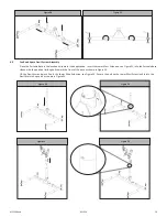
Page 9: ...17 Figure 18 Before inserting the legs into the base center section refer to the table in Figure 19 to match the Base Position with the Pin Position of the Davit Arm To install the Davit Base Legs ens...

Page 10: ...wer Mast Extension see Figure 22 into the Portable Base sleeve with the position limiting bolt toward the front of the base as shown in Figure 23 Lift the Davit Arm and place if onto the Lower Mast Ex...

Page 11: ...ure the anchor point is centered over the entry egress location To adjust turn the fine adjustment screw to raise and lower the arm to the desired position see Figure 27 Figure 26 Figure 27 4 8 Winch...

Page 12: ...able Routing If using a rear mounted device use the Top Pulley TP Run the line of the device over the rear pulley of the Davit Arm remove the detent pin and run the line over the top pulley and reinse...

Page 13: ...thoroughly for damage Inspection should include checking the structure for dents cracks deformed or bent tubing 6 1 3 Inspect all hardware for damage wear or missing parts 6 1 4 Check all rollers and...

Page 14: ...the Inspection Record provided below or on a similar document Inspection Record Model _________________________ Serial _________________________ Date of Manufacture _________________________ INSPECTI...

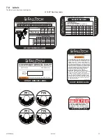
Page 15: ...20 120 ANGLES APPROVED MFG CHECKED SURFACE ROUGHNESS SURFACE FINISH 9 11 17 MATERIAL DRAWN N A N A N A 0 1 0 2 0 3 0 5 0 5 114 5mm 89mm DO NOT REMOVE LABEL 412 01651 Rev A OFFSET LENGTH AND LOAD RATIN...

Page 16: ...l Before Use DO NOT REMOVE LABEL www falltech com 63 5mm 95mm 40mm x 10 mm cut out window pantone solid coated colors pantone black C pantone 152C 1 2 3 4 A B C D THE INFORMATION EMBODIED IN THIS DOCU...

Page 17: ...o 30 30 to 120 120 ANGLES APPROVED MFG CHECKED SURFACE ROUGHNESS SURFACE FINISH 9 11 17 MATERIAL DRAWN N A N A N A 0 1 0 2 0 3 0 5 0 5 63 5mm 95mm 412 01650 Rev A DO NOT REMOVE LABEL This base is to b...

Page 18: ...TION EMBODIED IN THIS DOCUMENT IS STRICTLY CONFIDENTIAL AND ARE SUPPLIED WITH THE UNDERSTANDING THAT THEY WILL NOT BE DISCLOSED TO THIRD PARTIES 1 1 1 1 A A WEIGHT FOR REFERENCE ONLY N A N A N A Samue...

Page 19: ...he employer s managed fall protection program who through training and knowledge is capable of identifying evaluating and addressing existing and potential fall hazards and who has the employer s auth...

Page 20: ...automatically locks at the onset of a fall to arrest the user but that pays out from and automatically retracts onto the drum during normal movement of the person to whom the line is attached After on...

Page 21: ...Maximum Two Workers at up to 310 lbs Each 620 lbs Total for Rescue Configurations Maximum One Worker up to 310 lbs for Normal Confined Space Entry Egress Operations OSHA 1926 502 3pc Portable Base for...

Page 22: ...ible Lower Mast Extension 6500128 12 to 29 Offset Davit Arm 6500244 24 to 44 Offset Davit Arm 6500321 6500433 6500545 6500657 Lower Mast Extensions 6500728 3pc Portable Base for 12 to 29 Offset Davit...

Page 23: ...e mount Fixed Base SST for Confined Space Davit Yes Yes 65060FMZ Floor mount Fixed Base Zinc for Confined Space Davit Yes Yes 65060FMS Floor mount Fixed Base SST for Confined Space Davit Yes Yes 65070...

Reviews: