7.0 Inspection
7.1
Pre-Use User Inspection:
Perform an inspection before each use in accordance with the recommendations in Table 1 below.
Inspection Procedure
Pass
Fail
The cable lifeline should extract and retract completely and without faltering and should remain taut under tension without sagging.
Extract the cable lifeline several inches and apply a firm pull to confirm the SRD locks. The locking should be certain and without
skidding. Repeat this lockup at additional places along the lifeline length to confirm the SRD is operating correctly.
Examine the load indicator on the swiveling carabiner to be certain that it has not been loaded, impacted or activated; see Figure 15.
Inspect the entire length of the constituent line up to the Green Maximum Working Length Visual Indicator shown in Figure 16.
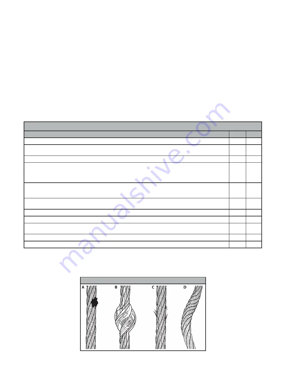
Review the cable lifeline closely for broken strand wires, welding spatter burns, welding slag, bird-caging, kinks and bent strands.
Also examine for rust, dirt, paint, grease or oil. Check for damage caused by chemical corruption or excessive heat as evident with
discoloration. See Figure 17 for examples. If any of these conditions exist, remove the SRD from service.
If during your line inspection defined above, you extract the line past the Green Indicator and ultimately expose a secondary Red
Indicator on the line, you must remove the SRD from service immediately. This Secondary Red Visual Indicator signals the SRD unit’s
Reserve Line has been deployed or the SRD has experienced a fall event and is no longer in working order.
Check the mode changing function by placing the SRL-R into Retrieval/Rescue mode and back to Fall Arrest mode to ensure proper
operation.
Check for any missing or loose screws or nuts and any deformed or damaged components.
Examine the external housing for cracks, breaks or warping.
Check the external Connector Eye and the Anchorage Carabiner for damage and deformation. The Anchorage Carabiner Gate should
twist open and snap shut easily and smoothly.
Examine the overall SRD unit for any indications of deterioration or damage.
All labels must be intact and legible.
Table 1 - Guidelines for Cable SRL-R Inspection
Extract all of the cable and check the entire working length for damage caused by chemical corruption or excessive heat as evident by
discoloration (A), bird-caging (B), broken wire strands (C), kinks and bent strands (D); see Figure 17. The cable should retract completely
without faltering and should remain taut under tension without sagging.
Figure 17 - Cable Inspection
MCS05 Rev A
121619
13
6.0 Maintenance, Service and Storage
6.1 Maintenance:
Ensure the SRL-R is kept free of excess paint, grease, dirt, or other contaminants as this may cause to the lifeline or
retracting mechanism to malfunction. Ensure no debris enters the housing through the cable access port. Clean the exterior of the unit as
required with a detergent/water solution. Do not allow corrosion causing elements to enter the housing. After cleaning, pull the
lifeline all the way out, allow the unit to air dry, then retract the lifeline into the unit. Do not allow the lifeline to freewheel back into
the housing. Clean labels as required.
DO NOT
use heat to dry.
DO NOT
attempt to disassemble the SRD.
6.2
Service:
If service is required for any reason; inspection failure, impact loaded, any type of malfunction, tag the unit as “UNUSABLE”,
store separately, and contact FallTech at 323-752-0066 to receive a Return Authorization number or to locate the nearest FallTech Service
Center. The SRL-R is not user repairable. Only the manufacturer, or a repair facility authorized in writing, may make repairs to the SRD.
This SRD is designed to be used installed in an anchor cradle or attached overhead.
6.3 Storage:
Hang the SRD in a cool, dry, clean environment out of direct sunlight. Position the SRD so excess water can drain out. Avoid
exposure to chemical or caustic vapors. Thoroughly inspect the SRL-R after any period of extended storage.


