

ENGLISH
41
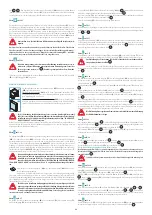
SAFETY INSTRUCTIONS AND WARNINGS
INSTALLATION WARNINGS
TECHNICAL SAFETY
Installation operations are to be carried out by skilled and qualiied install-
ers in accordance with the instructions in this booklet and in compliance
with the regulations in force.
•
Before installing the hood, check the integrity and function of each part. Should
anomalies be noted, do not proceed with installation and contact the Dealer.
•
Do NOT install the hood if an aesthetic defect has been detected. Put it back into
its original package and contact the dealer. No claim can be made for aesthetic
defects once the hood has been installed.
•
During installation, always use personal protective equipment (e.g. accident-prevention
shoes) and adopt prudent and proper conduct.
•
Keep in mind that installations with diferent types of ixing systems from those supplied,
or which are not compliant, can cause electrical and mechanical seal danger.
•
Do not modify the electrical, mechanical and functional structure of the equipment.
•
Do the install the hood outdoors and do not expose it to atmospheric agents (rain, wind,
etc.).
•
After the stainless steel hood has been installed, it will need to be cleaned to remove any
residues from the protection adhesive as well as any grease and oil stains which, if not
removed, can cause irreversible damage to the hood surface. To do so the manufacturer
recommends using the supplied moist wipes, which are also available sold separately.
ELECTRICAL SAFETY
The electrical system to which the hood is to be connected must be accord-
ing to standard and compulsorily supplied with earthed connection in
compliance with safety regulations in the country of use. It must also com-
ply with European standards regarding radio antistatic properties.
•
Before installing the hood, check that the electrical mains power supply corresponds
with what is reported on the identiication plate located inside the hood.
•
The socket used to connect the installed equipment to the electrical power supply must
be within reach: if this is not possible, install a mains switch in an accessible position in
order to disconnect the hood when required.
•
Any changes to the electrical system required to install the hood must be carried out by
a qualiied electrician.
•
It is dangerous to change, or try to change, the features of this equipment. Do not try
to solve the problem yourself in the event of equipment malfunction, but contact the
Dealer or an authorised Servicing Department for repairs.
•
If the power cable needs to be replaced by the Technical Servicing Department, use a
H05VV-F type cable with 3x0.75mm² section.
•
When installing the hood, disconnect the equipment by removing the plug or
switching of the main switch.
FUMES DISCHARGE SAFETY
•
Do not connect the equipment to discharge pipes of fumes produced from com-
bustion (for example boilers, ireplaces, etc.)
•
Before installing the hood, ensure that all standards in force regarding discharge of air out
of the room have been complied with.
•
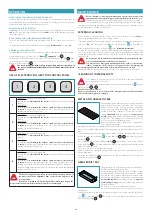
USER WARNINGS
GENERAL WARNINGS
These warnings have been drawn up for your personal safety and those of
others. You are therefore kindly asked to read the booklet carefully in its
entirety before installing and using the equipment or carrying out clean-
ing operations.
•
The Manufacturer declines all responsibility for any damage caused directly, or
indirectly, to persons, things and pets as a consequence of failing to comply with
the safety warnings indicated in this booklet.
•
It is imperative that this instructions booklet is kept together with the equipment
for any future consultation. If the equipment is sold or transferred to another per-
son, make sure that the booklet is also supplied so that the new user can be made
aware of the hood's operation and relative warnings.
•
Installation operations are to be carried out by skilled and qualiied installers in ac-
cordance with the instructions in this booklet and in compliance with the regula-
tions in force.
•
DO NOT use the hood if the power supply cable or other components are dam-
aged.
Disconnect the hood from the electrical power supply and contact the Dealer or
an authorised Servicing Department for repairs. Insist on original spare parts. Do not per-
sonally try to carry out repairs or replacements. Interventions carried out by incompetent
and unauthorised persons can cause damage, even serious, to things and/or persons not
covered by the Manufacturer's warranty.
•
Do not modify the electrical, mechanical and functional structure of the equipment. Any
changes to the electrical system required to install the hood must be carried out by a
qualiied electrician.
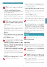
INTENDED USE
•
The equipment is solely intended to be used to extract fumes generated from
cooking food in non-professional domestic kitchens:
any other use is improper, can
cause damage to persons, things and pets and exempts the Manufacturer from any li-
ability.
The equipment must not be used in combination with gas cooker tops.
•
The equipment can be used by children above the age of 8 and by persons with reduced
physical, sensory and mental abilities, or with no experience or knowledge, as long as
they do so under supervision or after having received relative instructions regarding safe
use of the equipment and understanding of the dangers connected to it. Children are
not to play with the equipment. Cleaning and maintenance operations intended for the
user must not be carried out by children without supervision.
USE AND CLEANING WARNINGS
•
Before cleaning or carrying out maintenance operations, disconnect the equip-
ment by removing the plug or switching of the main switch.
•
Do not use the hood with wet hands or bare feet.
•
Always check that all electrical parts (lights, extractor fan) are of when the equipment
is not used.
•
The maximum overall weight of any objects placed or hung (if applicable) on the hood
must not exceed 1.5 Kg.
•
Check the deep-fryers during use: overheated oil can catch ire.
•
Do not light naked lames near to the hood.
•
Do not lambé foods near to the hood.
•
Never use the hood without the metal anti-grease ilters: in this case, grease and dirt will
deposit in the equipment and compromise its operation.
•
Accessible parts of the hood can be hot if used together with cooking appliances.
•
Do not carry out any cleaning operations when parts of the hood are still hot.
•
There can be a risk of ire if cleaning is not carried out according to the methods and
products indicated in this booklet.
•
Disconnect the main switch when the equipment is not used for long periods of time.
If other appliances that use gas or other fuels are being used at the same time
(boiler, stove, ireplaces, etc.), make sure the room where the fumes are extracted
is well-ventilated, in compliance with the current regulations.
WARNINGS IN CASE OF MALFUNCTION
•
DO NOT use the hood if the power supply cable or other components are dam-
aged.
Disconnect the hood from the electrical power supply and contact the Dealer
or an authorised Servicing Department for repairs. Insist on original spare parts.
Do not
personally try to carry out repairs or replacements. Interventions carried out by in-
competent and unauthorised persons can cause damage, even serious, to things
and/or persons not covered by the Manufacturer's warranty.
The Manufacturer reserves the right to make changes to the equipment at any time and
without prior notice. Printing, translation and reproduction, even partial, of this manual are
bound by the Manufacturer's authorisation.
Technical information, graphic representations and speciications in this manual are for infor-
mation purposes and cannot be divulged.
This manual is written in Italian. The Manufacturer is not responsible for any transcription or
translation errors.
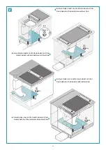
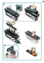
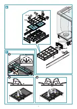
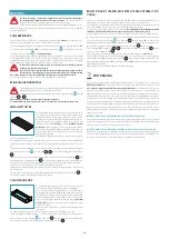
INSTALLATION
(only intended for personnel qualiied to install the hood)
Before installing the hood, carefully read chap. "Safety instructions and
warnings" on page 41.
TECHNICAL FEATURES
The technical speciications are reported on the identiication plate located inside the hood.
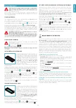
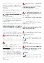
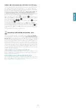
POSITIONING
The hood can be installed next to the cooker top (standard installation) or far from it.
The minimum distance between the cooker top and the hood, should the two parts not be
installed next to each other, must not be less than 50mm (2"), and must nevertheless take
into account the resistance of the worktop.
This is also the recommended distance: in certain cases, this distance can be increased up
to a maximum of approximately 100mm (4"), with a slight decrease in the eiciency of the
device.
Do not install the hood outdoors and do not expose it to atmospheric agents (rain, wind,
etc.).
It is strongly recommended to put any wall cabinets above the cooking
area at a distance of at least 65cm from the worktop so that the moisture
generated by the cooking and the higher temperatures do not compro-
mise the aesthetic appearance and the integrity.
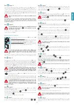
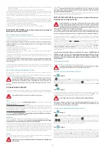
ELECTRICAL CONNECTION
(only intended for personnel quali-
ied to install the hood)
Disconnect the equipment from electrical mains power supply before car-
rying out any operations on the hood.
Make sure that the wires inside the hood are not disconnected or cut.
Should this occur, contact your nearest Servicing Department. Refer to
qualiied personnel for electrical connections.
Connection must be carried out in compliance with the provisions of law in force.
Before connecting the equipment to the electrical mains power supply, check that:
•
voltage supply corresponds with what is reported on the identiication plate located
inside the hood;
•
the electrical system is compliant and can withstand the load of the equipment (refer to
the technical speciications on the identiication plate located inside the hood);
•
once connected, the plug and cable do not come into contact with hot parts having
temperatures that exceed 70°C;
Summary of Contents for piano
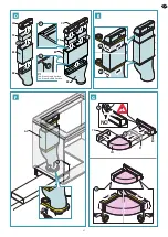
Page 24: ...24 A1 217mm 87mm UM X F 1 3 Y 2 A2 KDC F UM UM...
Page 28: ...28 3 2 1 EV A UA B D C V2 x4 5 CP OK OK Crack E 4 6 H...
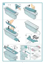
Page 29: ...29 1 3 V3 G 4 5 V3 G 2 OK D CP 5 4 1 3 V2 x4 CS CD 2 Piano Double Suction I L...
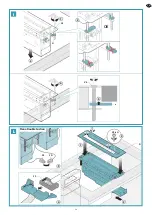
Page 30: ...30 M 2 OK 1 3 AB UA V2 EC CV 4...
Page 31: ...31 3 EV 4 1 2 B A CM CC 1 2 N O...
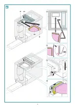
Page 33: ...33 Q 4 5 6 3 2 1 EV A UA B C B...
Page 34: ...34 1 2 3 4 5 6 FK AF A V5 x5 R S 3 2 45 90 45 90 45 1...


