

ENGLISH
43
Phase
B2
on page
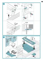
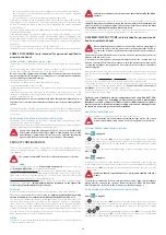
To be able to install the optional "Piano under furniture carbon-zeo ilter (
KF
)” kit and to be
able to perform the subsequent maintenance operations, a minimum available space of
1100mm is required, including the motor unit clearance (
UM
) and the optional "Piano under
furniture carbon-zeo ilter (
KF
)” kit. In relation to the dimensions of the furniture, to the type
of installation of the cooking area (wall or island) and to the required air output direction, it is
possible that the air output itting of the motor unit (
UM
) is partly aligned with the furniture
legs and it is therefore necessary to move some.
Make sure that this operation does not compromise stability of the fur-
niture.
To avoid this problem or to position the optional "Piano under furniture carbon-zeo
ilter
(KF)" kit in a position which allows easier maintenance, the optional “Double
horizontal curve (KDC
)
” kit is available, whose dimensions are shown in the technical
speciications on page 9
on page
To install the iltering version hood one or more suitably sizes holes must
be drilled in the kitchen plinth (
Fig.
1
), to allow puriied air to exit the
under furniture compartment.
For this reason two air grilles (
GA
) are supplied together with the optional "Piano under
furniture carbon-zeo ilter (
KF
) kit.
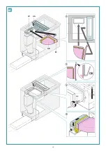
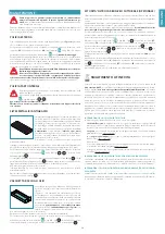
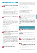
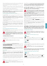
REMOTE MOTOR UNIT (URS OR URE)
The hood can be connected to the under-roof (
URS
) and outdoor (
URE
)
remote motor unit .
In the case of an under-roof motor unit (
URS
), it must be placed next to
the technical compartment inside the home, protected against atmos-
pheric agents and within reach for any maintenance operations.
In the case of an outdoor motor unit (
URE
), it is recommended to ind a
position protected from rain, snow, wind, etc., in order to prevent rain and
humidity from entering, which can damage the outdoor unit.
To connect the hood with an under-roof (URS) or outdoor (URE) remote
unit a conveyor kit must always be installed: read chapter “
” on page
to choose the most suitable conveyor
kit.
The dimensions of any drawers or baskets can be taken into account for this type of instal-
lation so as to assess which conveyor to assemble, as there is no under furniture motor unit.
on page
Prepare the suction pipe (
FR
) for connection of the hood to the under-roof (
URS
) or out-
door (
URE
) remote unit: preferably use pipes with rectangular sections of suitable sizes and
install them as an end part to be connected to the "Rectangular circular curve (
KACL.371
)"
conveyor kit (sold separately). Position the piping with reference to the furniture on the basis
of the heights (X and Y) indicated on the irst pages of this booklet, by using the centre of
the circular itting of the
KACL.371
part as a reference. Prepare a piece of pipe with circular
section (
F
) to allow subsequent assembly of the conveyor kit.
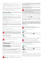
To install the hood with remote motor unit, the type of suction pipes used
and their position can vary considerably: in some cases it may not be nec-
essary to drill a hole on the bottom of the furniture having the sizes indi-
cated on the speciications “
SPECIFICATIONS AND SET-UP FOR WALL UNIT
To assemble the under-roof (
URS
) or outdoor (
URE
) remote motor unit, refer to the
relative instructions booklet.
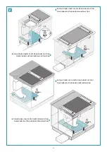
Once the under furniture motor unit has been positioned or connection of the
suction pipe for the remote motor unit has been prepared, the assembly instructions of the
conveyor and the hood are generic, the diference being only whether there is a Piano Single
Suction hood or a Piano Double Suction hood.
To correctly install the hood the rectangular connection pipes, cut to the
right length, between the various ittings must be prepared: refer to the
technical speciications inserted in the irst pages of this booklet and to the
speciications
“Set-up for installation: examples of installation”
shown
from page
to page
on page
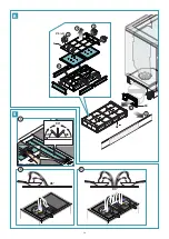
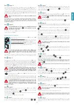
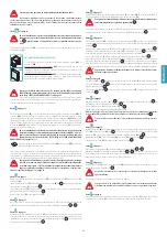
Assemble on the ground the set consisting of the conveyor kit (
KC
), the silencer (
ES
), the
vertical pipe (
T3
) and the curve (
CV
).
Insert the silencer (
ES
) directly in the conveyor kit (
KC
)(Fig.
1
); block the two parts using
the self-threading screws (
V1
) supplied (Fig.
2
).
Insert the vertical pipe (
T3
) in the silencer: there are metal hooks inside it which ensure
correct positioning (Fig.
3
).
Lastly, assemble the curve (
CV
) on the vertical pipe (
T3
).
Afterwards seal all joints with adhesive tape (supplied) to prevent any accumulation of con-
densation from seeping through the coupling joints of the various parts (Fig.
4
and
5
).
URS
URE
Carefully place the assembled set (
AC
) in the furniture by inserting the circular itting of the
conveyor kit in the circular itting of the under furniture motor unit or in the circular pipe (for
connection with remote motor unit) prepared previously (Fig.
1
); also seal this joint with the
adhesive tape supplied (Fig.
2
).
Next, prepare the set consisting of the horizontal pipe (
T2
), the curve (
CO
), eventual pipe
(
T1
) present only in some types of installation, and the conveyor part (
EC
).
To insert the conveyor part (EC), do not remove the protective ilm of the
seal ring (Fig.
2
).
Seal all joints with adhesive tape (supplied) to prevent any accumulation of con-
densation from seeping through the coupling joints of the various parts (Fig.
3
).
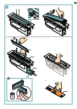
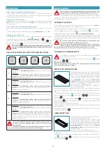
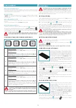
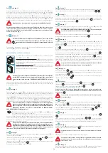
Remove the part with the adjustable laps (
EV
) from the suction unit (
UA
): proceed with
caution, taking care to irst lift the front and then removing the two pins in the rear part
(Fig.
2
).
Remove the metal anti-grease ilter (
A
), the drilled part (
B
) and the grease drip tray (
C
) (Fig.
3
).
Disconnect the push button control panel connector (
CP
) as shown in (Fig.
4
) (for the
Piano Double Suction hood, only for the suction unit equipped with push button control
panel).
Remove the stainless steel frame (
D
) assembled on the suction unit by turning the 4 screws
(
V2
) (Fig.
5
).
Before inserting the hood in the worktop, for some types of installation it is necessary to
remove the knockouts (
E
) on the suction unit (Fig.
6
); these parts are necessary to prevent
the liquid from leaking from the cooker top inside the furniture and as a support part of the
top itself, but are to be removed from the side supporting the worktop and in the event of
cooker tops with unsuitable dimensions.
The knockouts must always be removed after having irst removed the
stainless steel frame.
on page
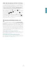
Turn the screws (
V3
) (Fig.
1
) to position the ixing elements (
G
) of the suction unit in the
position shown in (Fig.
2
) to allow the hood to be inserted in the hole drilled in the work-
top (Fig.
3
).
Tighten all screws (
V3
)(Fig.
4
) to lift the ixing elements (
G
) and block the hood on the
worktop (Fig.
5
).
on page
Reassemble the stainless steel frame (
D
) (Fig.
1
) using the screws (
V2
) removed previously
(Fig.
2
) and reposition the grease drip tray (Fig.
3
).
Reconnect the push button control panel connector (
CP
) (Fig.
4
).
Only for Piano Double Suction hood version
Connect the connector (CS) from the suction unit not provided with controls to the
corresponding connector (CD) positioned in the suction unit with push button con-
trol panel (Fig.
5
).
If this operation is not carried out, operation of the hood motor is prevent-
ed.
on page
Install the previously assembled set (
AB
), simultaneously coupling it in the suction unit (
UA
)
and the curve (
CV
) (Fig.
1
): make sure the fold on the rear of the conveyor part (
EC
) its into
the hole on the suction unit (
UA
)(Fig.
2
).
Lock the set (
AB
) to the suction unit (
UA
) with the screws (
V2
) supplied (Fig.
3
) and seal
the joint made with the curve (
CV
) with the adhesive tape supplied (Fig.
4
) .
on page
Reposition the drilled part (
B
) and the metal anti-grease ilter (
A
) (Fig.
1
and
2
).
Reassemble the part with the adjustable laps (
EV
) (Fig.
3
and
4
): proceed with caution,
taking care to correctly insert the two pins in the rear part in the corresponding holes on the
stainless steel frame of the suction unit.
Connect the hood connector (
CC
) to the connector (
CM
) on the under furniture extractor
fan or coming from the remote motor unit (Fig.
1
).
The electrical junctions and the connection couplings must not be accessi-
ble after installation.
Electrically power the hood in accordance with regulations in force.
The hood is supplied with a safety device which prevents operation of the
motor should the adjustable laps of the suction unit be in the closed posi-
tion.
Cover the hole on the bottom of the furniture with the langes (
FF
) supplied: secure them
using the appropriate screws (
V4
) following the indications relative to the type of installation
carried out.
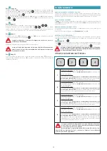
Summary of Contents for piano
Page 24: ...24 A1 217mm 87mm UM X F 1 3 Y 2 A2 KDC F UM UM...
Page 28: ...28 3 2 1 EV A UA B D C V2 x4 5 CP OK OK Crack E 4 6 H...
Page 29: ...29 1 3 V3 G 4 5 V3 G 2 OK D CP 5 4 1 3 V2 x4 CS CD 2 Piano Double Suction I L...
Page 30: ...30 M 2 OK 1 3 AB UA V2 EC CV 4...
Page 31: ...31 3 EV 4 1 2 B A CM CC 1 2 N O...
Page 33: ...33 Q 4 5 6 3 2 1 EV A UA B C B...
Page 34: ...34 1 2 3 4 5 6 FK AF A V5 x5 R S 3 2 45 90 45 90 45 1...


