17
ENGLISH
•
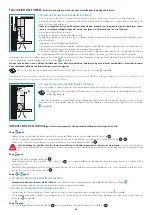
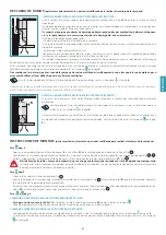
With external exhaust (suction) versions, it is possible to insert extension (
H
) with the slots facing downwards so that they are not visible when
the installation height allows it.
Phase
•
Slide the extension (
H
) until it is positioned at the desired height (Fig.
1
).
•
Following what is indicated in Fig.
2
, draw a line on the wall that will be used to position the bracket (
L
) correctly.
•
Place the bracket (
L
) on the wall by following the line drawn on it. With a spirit level, check the horizontal alignment and mark the 2 drilling points
at the ends (Fig.
3
).
•
Drill the holes, insert 2 expansion plugs (ø 6mm) and fasten the bracket (
L
) with the relative screws (
V4
) (Fig.
4
).
•
Tighten the extension (
H
) to the bracket (
L
) using screws (
V5
) (Fig.
5
).
•
Electrically power the hood in accordance with regulations in force.
OPERATION
WHEN SHOULD THE HOOD BE SWITCHED ON AND OFF?
Switch on the hood at least one minute before starting to cook: this enhances the airlow to convey fumes and vapours towards the suction surface.
After cooking, leave the hood operating until complete extraction of all vapours and odours. If required, by means of the Timer function, it is possible
to set hood auto switch-of after 15 minutes of operation.
WHICH SPEED IS TO BE SELECTED?
The
irst
speed is a low consumption energy-saving way of keeping the air clean, the
second
speed is used in normal conditions, and the
third
speed is used when there are strong odours and vapours.
WHEN SHOULD THE FILTERS BE WASHED OR REPLACED?
The hood is assembled with two diferent types of ilters: metal ones (washable) and active carbon ones (non-washable). The former must be
cleaned every 30 hours of use (the ixed red light
indicates that they need to be washed), the latter are to be replaced every 3-4 months, de-
pending on the use of the hood. For further information, please read the chapter regarding "
on page
.
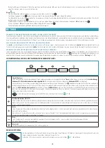
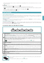
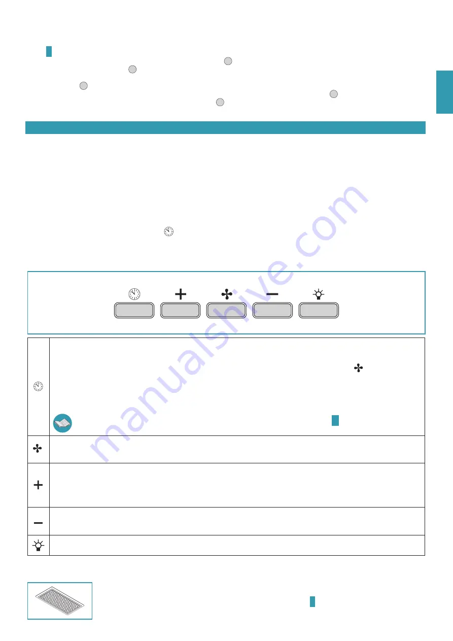
USE OF ELECTRONIC PUSH BUTTON CONTROL PANEL
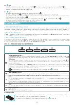
Timer/Filters alarm
Pressing the key with the motor active at any speed activates the
Timer
function: this function determines the
auto switch-of of the
hood after 15 minutes of operation
. Activation of the function is signalled by a
RED lashing
light.
With the Timer function active, the hood can still be switched of by the user at any time by pressing the key
: the function will be
automatically disabled and the RED light will turn of. Should the speed be changed with the Timer function active, the latter will be
automatically disabled.
On the other hand, ignition of the
ixed RED
light indicates a
grease ilter alarm
: this alarm notiies that it is time to wash the metal
anti-grease ilters (the alarm is triggered after approximately 30 hours of use). After cleaning the ilters, disable the alarm and reset the
counters by keeping the key pressed for 3 seconds.
To disassemble and assemble the anti-grease metal ilters, refer to the instructions on drawing
Mode button (ON/OFF)
Pressing the key switches on (or of ) the hood motor: it starts at the previously selected speed prior to switching it of (desired speed
function). Should you wish to use a diferent speed, set if by using the + and - keys.
By pressing the key, the motor speed increases. Speeds 1, 2 and 3 are displayed by the number of LEDs switched on, excluding the light
and timer LEDs.
The + key in the version with 4 speeds has an intermittent light: the 4th speed or intensity is timed and after approximately 7 minutes the
motor automatically switches to 3rd speed.
Button -
By pressing the key, the motor speed reduces. Speeds 1, 2 and 3 are displayed by the number of LEDs switched on, excluding the light
and timer LEDs.
Light button
ON: light on (lit button) OFF: light of
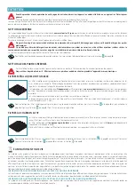
LIGHTING
The range hood is equipped with high eiciency, low consumption LED spotlights with extremely long duration under
normal use conditions.
Should the LED spotlight need to be replaced, proceed as shown in the igure
on page
.
Summary of Contents for PLANE
Page 5: ...5 5 L H V5 x2 3 L L H 4 6 mm 6 6 V4 x2 1 2 E F G H V3 x6 1 2...
Page 6: ...6 1 2 3 4 5 MAGNETE MAGNET G 1 2 3 1 2 2 12V 1 2 3 H I L...
Page 34: ...34 2 10 Il l 8...
Page 35: ...35 1 5 34 A 4 65 25 6 EN60335 2 31 11 07 2002 TC61 7 12 1 15 10 11 70 C III...
Page 37: ...37 F 5 H 1 2 L L 3 2 6 L V4 4 V5 H L 5 15 30 3 4 38 15 30 3 H 6 1 2 3 4 4 7 3 1 2 3 L 6...
Page 38: ...38 15 Fasteel G 6 1 55 C G 6 H 6 3 4 G 6 H 6 I 6 E C WEEE...
Page 75: ......


