


28
Before connecting the equipment to the electrical mains power supply, check that:
•
voltage supply corresponds with what is reported on the identiication plate located
inside the hood;
•
the electrical system is compliant and can withstand the load of the equipment (refer to
the technical speciications on the identiication plate located inside the hood);
•
once connected, the plug and cable do not come into contact with hot parts having
temperatures that exceed 70°C
•
the power supply system is efectively and properly connected to earth in compliance
with regulations in force.
the socket outlet to connect the installed equipment is within reach.
Some types of equipment can be equipped with a cable without a plug; in this case, the
type of plug to use is a "standardised" one, keeping in mind that the yellow-green wire must
be used for earthing, the blue wire must be used for neutral, and the brown wire must be
used for the phase.
The power supply cable must be assembled with a plug suitable for the load and connected
to an adequate safety plug.
If the ixed equipment is not provided with a power supply cable and plug, or any other
device that ensures disconnection from the electrical mains, with an opening gap of the
contacts that enables total disconnection in overvoltage category III conditions, said discon-
nection devices must be provided in the mains power supply in compliance with installation
regulations.
The yellow/green earth cable must not be cut of by the switch.
The Manufacturer declines all responsibility for failure to comply with the safety regulations.
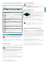
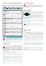
FUMES DISCHARGE
(only intended for personnel qualiied to assemble the hood)
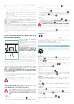
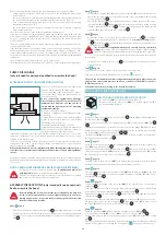
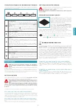
EXTERNAL EXHAUST HOOD VERSION (SUCTION)
In this version, the kitchen fumes and vapours are
conveyed outside through an exhaust pipe.
The air outlet itting of the motor must be connect-
ed to the pipe that conducts the fumes and vapours
to an external outlet.
Do not connect the equipment to discharge
pipes of fumes produced from combustion (for
example boilers, ireplaces, etc) and you are to
comply with the regulations in force regarding
external air discharge.
The fumes outlet pipe must have:
- a diameter, or diameters, not less than that of the
hood itting
- a slight slope downwards (drop) in the horizontal
sections to prevent any formation of condensation
from lowing back to the hood;
- the minimum required number of bends;
- minimum required length (long pipes with various
bends can reduce suction performance of the hood
and trigger vibrations of the check valve).
If the fumes outlet pipe passes through cold environments such as attics, etc., it is possible
that water condensation forms due to sudden changes in temperature. In this case, you are
required to insulate the pipes.
The hood is supplied with a check valve whose function is to prevent any external air ex-
change when the hood is not operating: for further information, refer to the assembly in-
structions chapter on page
.
When the kitchen hood is used simultaneously with other appliances that use gas or
other fuels, the room must have suicient ventilation, in accordance with regulations
in force.
Deviation for Germany: when the kitchen hood is used at the same time as appliances that are
powered by energy other than electricity, the negative pressure in the room must not exceed 4 Pa
(4 x 10⁻⁵ bar).
HOOD VERSION WITH INTERNAL RECIRCULATION (FILTERING)
The iltering version hood can only be used if the
“Unità iltrante a soitto” kit
(sold separately)
has been installed downstream the motor.
In this model, air passes through the carbon-zeo combined ilters to be puriied
and is then recycled into the kitchen environment.
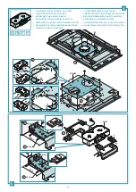
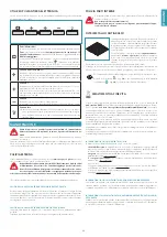
ASSEMBLY INSTRUCTIONS
(only intended for personnel quali-
ied to assemble the hood)
Before installing the hood, make sure the false ceiling has been duly rein-
forced to safely support the device: the weight of the hood, in various as-
sembly conigurations, is reported in the technical speciications inserted
in the irst part of this booklet.
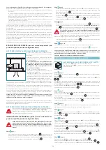
Phase
•
Make a hole in the false ceiling as indicated in Fig.
2
(for drilling dimensions, refer to the
technical speciications inserted in the irst part of this booklet). Should the plasterboard
have reinforced proiles, keep a minimum distance of 60mm from the drilling perimeter
(Fig.
1
).
Phase
•
Check that the supplied laps (
H
) of the protection template (
G
) are bent on the opposite
side to the one with the double-sided adhesive tape. If not, bend them with a suitable
tool (e.g. grippers) (Fig.
1
).
•
Remove the ilm from the doubled-sided adhesive tape already applied on the protec-
tion template (
G
) (Fig.
2
) and insert it into the hole made on the false ceiling, keeping
it tilted so that it passes easily (Fig.
3
). Complete the operation by ixing the protection
template (
G
) to the plasterboard false ceiling (Fig.
4
).
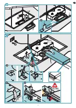
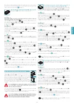
Phase
•
Measure the distance of the safety holes on the hood (X and Y - Fig.
1
). According to
the measurements obtained, mark two drilling holes on the
masonry ceiling
(X and Y -
Fig.
2
). Drill a ø9 mm hole in line with the marked points and insert the supplied screw
anchors and eyes (Fig.
3
).
The screw anchors supplied with the hood can only be used on masonry
ceilings:
should it be necessary to install the hood on ceilings of diferent mate-
rial, assess other ixing systems, keeping the wall's strength and the weight of the
hood in mind (indicated in the technical speciications inserted in the irst part of
this booklet).
•
Fasten the safety chains to the eyes (Fig.
4
); they will then be fastened to the hood as
a safety support.
Fase
pag. 10
Open the external suction panel of the hood and remove it completely.
Then remove the anti-grease metal ilters (see instructions
U
on page 20).
The hood can be installed in various conigurations, depending on where the motor
unit is placed (motor unit placed on the hood or under-roof unit (URS) or outdoor
(URE) remote motor).
Follow the instructions according to the desired installation.
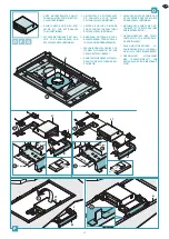
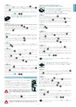
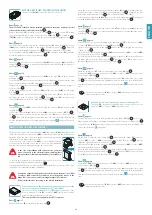
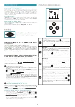
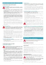
MOTOR UNIT PLACED ON THE HOOD
MOTOR UNIT (UM) PLACED ON THE HOOD
The motor unit (
UM
) is connected directly to the hood.
The motor used in the motor unit (
UM
) is, by default, equipped with a
check valve already installed.
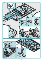
Phase
Remove the lange (FC) assembled on the hood (Fig.
1
) and the lange (FM) assembled on
the motor unit (UM) (Fig.
2
).
Deine the air outlet direction by rotating the lange (
FL
) of the motor unit (
UM
) (Fig.
3A
-
3B
).
To enable any maintenance operations, once the position of the lange (
FL
) has been deter-
mined, before securing it to the component (
FLF
), remove the two fastening screws from
the element (
SM
), as indicated in the igures
3A
-
3B
.
The motor unit (
UM
) can also be installed on the hood in various positions in order to have
the desired air outlet direction (Fig.
4
).
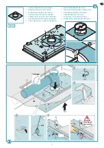
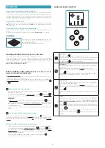
Phase
Check the correct position between the elements (
L
) and (
M
), which form part of the motor
unit (
UM
) support brackets (Fig.
1
).
If required, position them at the height indicated in (Fig.
2
) and secure them with 8 screws (
V1
).
Secure the support brackets (
L+M
) to the motor unit (
UM
) using the 4 screws (
V2
), taking
the desired air outlet direction into consideration (Fig.
3
)
Phase
The motor used in the motor unit (
UM
) is, by default, equipped with a check valve already
installed. If required, remove them from the air outlet itting of the motor.
Phase
page 12
Place the assembly composed of the motor unit (
UM
) and its supports (
L+M
) on the false
ceiling (Fig.
1
), taking care to centre the assembly by means of the laps (
H
) of the protec-
tion template (
G
) (Fig.
2
).
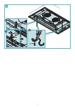
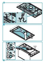
Phase
page 13
Connect the air outlet itting of the motor unit (
UM
) to the pipe (
F
) set up for external dis-
charge (Fig.
1
).
Set up the electric connection to power the hood only after having disconnected the main
power supply switch and complied with current regulations (Fig.
2
).
Lift the hood towards the false ceiling (Fig.
3
) and pass the chains through the safety holes
of the hood (Fig.
4
).
Insert the hood in the previously reinforced false ceiling: as the hooks (
G
) open, they provision-
ally support the hood on the false ceiling (Fig.
5
). Tighten all screws (
V3
) in order to open
the hooks (
G
) and block the hood on the false ceiling (Fig.
6
).
Phase
page 13
Fasten the motor unit (
UM
) to the hood body using the 8 screws (
V5
) (Fig.
1
).
Connect the motor unit (
UM
) connector (
CM
) to the hood connector (
CE
) (Fig.
2
).
Fix the safety chains to the hood using the supplied screws (
V4
) and cut the excess chain
(Fig.
3
).
Place back the anti-grease metal ilters removed earlier and then carefully place back the
external suction panel by conducting the steps in phase
C1
on page 10 in reverse order.
Summary of Contents for stella
Page 7: ...7 800 m3 h 950 m3 h 9 mm...
Page 9: ...9 X Y X 1 2 Y 4 3 9 mm C...
Page 16: ...16 3 V4 1 V5 x4 V6 x4 CM CE 2 N2...
Page 20: ...20 CUE CE 1 V4 2 S2 T MAGNETE MAGNET 3 1 2 U...
Page 47: ...47 8 47 110 43 3 150 59 65 25 5 EN60335 2 31 11 07 2002 TC61 7 12 1 15 10 11...
Page 50: ...50 15 30 51 Stella 4 5 433 92 1 2 1 4 5 5 2 2 10 5 2 ON OFF 1 1 2 3 4 4 7 3 1 1 2 3 4 1 15...
Page 51: ...51 15 1 2 3 4 4 7 3 1 2 3 15 Magic Steel 1 55 C T 20 U 20 RAEE RAEE...
Page 87: ...NOTE NOTES...


