background image

Installation Manual Essentials 120213 


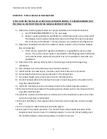
INSTALLING THE OUTSIDE AIR INTAKE LOUVER AND DAMPER BOX 

 
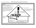
Identify the main return duct at the point after any secondary returns feed into the main 
return.  This is where the damper box will be installed.  (Install the damper box to allow for the 
shortest and straightest duct runs possible.) 

Move the Damper Box to the installation location. Be careful when moving the damper box to 
the attic as to not damage the damper or damper actuator.   

Install the gable vent and transition, (outside air intake,) on the North side of the building.  If 
this is not possible, install the gable vent on the West or East side.  Installing the gable vent on 
the South side may significantly degrade system performance.  If installation on the North, 
West or East side are not possible, FAMCO recommends using a rooftop intake. Preferred 
orientation for roof vents is the same as for gable vents. 
 
Connect a flex duct from the intake transition to the FRESH AIR port on the Damper Box. 
 
Cut the main return duct in a location that will allow re-connection to the damper box.  (The 
damper box will replace a section of duct, so the duct may need to be shortened to prevent the 
restriction of return air.) 
 
Connect the return duct to the RETURN port on the damper box. 
 
Connect the duct leading to the fan to the FAN port on the damper box. 
 
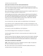
Install the butterfly damper and make it is oriented so gravity pulls it closed when not held 
open by airflow. 


Identify the damper cable. (Has a large gray and orange connector that connects to the damper 
box connector.) Connected to the Damper Box quick connect plug. Run the other end of the 
damper cable to the location where the Logic Box will be installed in the conditioned space. 

INSTALLING THE OUTDOOR AIR THERMOSTAT 

IDEAL

 - Install on North side of structure:  Shielded from all direct sunlight.  Not adjacent to 

attic space. Accessible by occupant and for service.  

OK

 - Install on West side of structure. Shielded from all direct sunlight, (would require a 

ventilated enclosure.) Not adjacent to attic space. 


Summary of Contents for ECONOMIZER BREATHE SMARTER

Page 1: ...Installation Manual Essentials 120213 BREATHE SMARTER TM PATENT PENDING...

Page 2: ...g HVAC system is functioning properly before beginning installation 4 Place damper box in the location where it will be installed 5 Install outside air intake louver transition and connect flex duct t...

Page 3: ...TANT Turn off the HVAC system at the breaker box before beginning installation Do not use the existing furnace transformer to power the IAQ Economizer The furnace transformer is not sized to support p...

Page 4: ...CAN BE EASILY ACCESSED BY OCCUPANT OUTSIDE AIR TEMPERATURE THERMOSTAT EXISTING FURNACE BOARD OUTSIDE AIR FLEX DUCTWORK ADDED NOT PROVIDED IN KIT IMPORTANT MINIMIZING TURNS AND BENDS IN DUCTWORK IS CRI...

Page 5: ...duct from the intake transition to the FRESH AIR port on the Damper Box Cut the main return duct in a location that will allow re connection to the damper box The damper box will replace a section of...

Page 6: ...VAC only Other sources of power will damage the unit DO NOT power the unit with power from the AC unit The furnace transformer will not have sufficient capacity to provide for the IAQ Economizer Provi...

Page 7: ...T cable are terminated correctly before plugging it into the Logic Box Connect the Power Cable to the Logic Box IMPORTANT There is one auxiliary connection that is required for the Logic Box to functi...

Page 8: ...Step 1 2 2 efore Furnace Board After To Logic Box To Thermostat Condensing Unit Yellow Yellow Green Green White Red Condensing Unit Yellow Green Red White To Thermostat Condensing Unit Yellow Yellow...

Page 9: ...Installation Manual Essentials 120213 8 STEP 3 Plug the other end of the furnace cable into the logic box connection marked FURNACE...

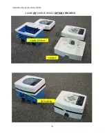
Page 10: ...Installation Manual Essentials 120213 9 3 GANG OR SURFACE MOUNT OPTIONS FIGURE 3 3 GANG FLUSH SURFACE E SET SCREW...

Page 11: ...use the Override OVRD switch to initiate an air introduction If the Yellow light went out before you switched the OVRD switch and the Red light lit wait 90 seconds The Green light should light indicat...

Page 12: ...pen the damper box as expected there are four items that should be checked 1 IAQ Economizer switch may be OFF 2 LIMIT Switch is OPEN or no jumper is installed 3 Outdoor thermostat setting requirements...

Page 13: ...Installation Manual Essentials 120213 12 All components of the IAQ Economizer are tested before shipping...

Page 14: ...NSFORMER CAPACITY IS 50VA LOGIC BOX TRANSFORMER TYPICALLY CONSUME LESS THAN 20VA DEVICES USING PWR OUT CANNOT EXCEED 50VA TOTAL TRANSFORMER CAPACITY EXTERNAL DEVICES PROVIDING A POWERED SIGNAL TO THE...

Page 15: ...using AUX START 1 Typical Uses Outdoor air low or high limit outdoor humidity or dew point limit Multiple devices need to be wired in series T2 Input used to allow a different setpoint to call for ec...

Page 16: ...ction is allowed Multiple devices need to be wired in parallel POWER Power simply provides 24 VAC that can be used to power other control devices used with the system The top terminal is 24VAC the bot...

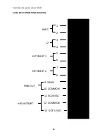
Page 17: ...Installation Manual Essentials 120213 16 AUXILLIARY CONNECTIONS FIGURE 5 LIMIT T2 EXT START 2 PWR OUT HRV INTRUPT EXT START 1 13 NOT USED 12 COMMON 11 ECON SIG 10 COMMON 9 24VAC 8 7 6 5 4 3 2 1...

Page 18: ...LIMIT CONDITIONS MET SYSTEM ON STAT CALLING EXT START 2 ON DAMPER CORRECT OPEN DAMPER S FAN ON COMPRESSOR ON YES YES YES YES YES YES YES NON ECON SUPPORTED COOL CALL YES ERROR INDICATION NO DAMPER PO...

Reviews: