Installation Manual Essentials 120213
6
All terminal plugs on the Logic Box can be removed from the Logic Box board. Use a screw
driver to gently pry them loose. Terminate wires before reconnecting plugs to the board.
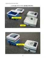
Install mounting plate to 3-gang box or wall.
Bring cables pulled earlier; Damper Cable, Power Cable, Furnace Cable, Outdoor thermostat
(OSAT) Cable through the mounting plate.
Connect the Damper Cable to the Logic Box termination labeled "Damper Cable."
Connect the Furnace Cable to the relay logic box termination labeled "Furnace Cable."
Connect the OSAT Cable to the 3 conductor plug provided with the kit. The thermostat wires
are connected to the bottom two terminations on the plug. The top terminal is provided as a
drain. It should be connected to the uninsulated shield conductor, 3
rd
conductor of the OSAT
wire.
IMPORTANT:
Verify that the wires of the OSAT cable are terminated correctly before
plugging it into the Logic Box.
Connect the Power Cable to the Logic Box.
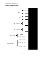
IMPORTANT: There is one auxiliary connection that is required for the Logic Box to function.
This is the LIMIT termination.
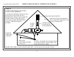
See FIGURE 4.
FAMCO recommends that appropriate safety
switches be installed for the climate at the installation site.
Recommended limits include low
temperature and humidity limits.
Selection and installation of appropriate limits is the
responsibility of the system installer
.
It is at the contractors’ discretion if they choose to “Jump-out” this connection to enable the
system to function without safeties installed. To jump-out safeties install a wire connecting
terminal 1 to terminal 2. See Figure 4.
FAMCO recommends the installation of an indoor low limit with all installations. This addition
greatly expands both the functionality and energy savings delivered by the system. Figure 4
also shows the installation of an indoor low limit thermostat.
Attach the Logic Box to the Mounting Plate using the set screw and wrench provided.

