Chapter 4 Electrical Installation
Shenzhen Hpmont Technology Co., Ltd.
- 18 -
HD3N-L Series User Manual V1.0
4.6.2
Wiring Requirement
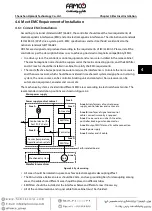
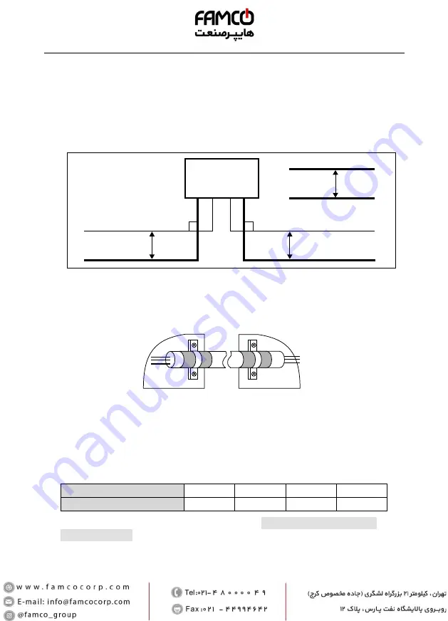
In order to avoid interference intercoupling, it is recommended to separate the power supply cables,
motor cables and the control cables, and keep enough distance among them, especially when the
cables are laid in parallel and are long enough.
The signal cables should cross the power supply cables or motor cables, keep it perpendicular (90
°
) as
shown in Figure 4-5.
Distribute the power supply cables, motor cables and control cables in different pipelines.
Figure 4-5 System wiring
Shielded or armoured cable: High frequency low impedance shielded cable should be used. For
example: Copper net, aluminum net or iron net.
Normally, the control cables must use the shielded cables and the shielding metal net must be
connected to the metal enclosure of the controller by cable clamps as shown in Figure 4-6.
Figure 4-6 Shielded cable connection
4.6.3
Motor Connection
The longer motor cable is, the higher carrier frequency will be, causing the high harmonic leakage
current on the cable to increase as well. This may affect peripheral devices.
When the motor cable length is longer than 100 meters, it is recommended to install AC output reactor
and adjust the carrier frequency according to Table 4-5.
Table 4-5 Carrier frequency and the cable length betweencontroller and motor
Cable Length
<30m
30 - 50m
50 - 100m
≥100m
Carrier Frequency
Below 15kHz
Below 10kHz
Below 5kHz
Below 2kHz
The cross sectional area (CSA) of motor cable should refer to section 4.2 Peripheral Accessories
Selection, on page 11.
The controller should be derated if motor cables are too long or their CSA is too large. The current
should be decreased by 5% when per level of CSA is increased. so do the leakage current to ground
and capacitance.
Controller
Power supply cable
Power supply cable
Motor cable
Motor cable
Control cable
Control cable
90°
>20 cm
90°
>50 cm
>30 cm
PE
PE
Enclosure
Enclosure


