background image

Fanaway Corbelle Installation Instructions


20  | 

P a g e                                                                   V E I L        

                                V e r s i o n 1 . 0   0 4 / 2 0 2 1  


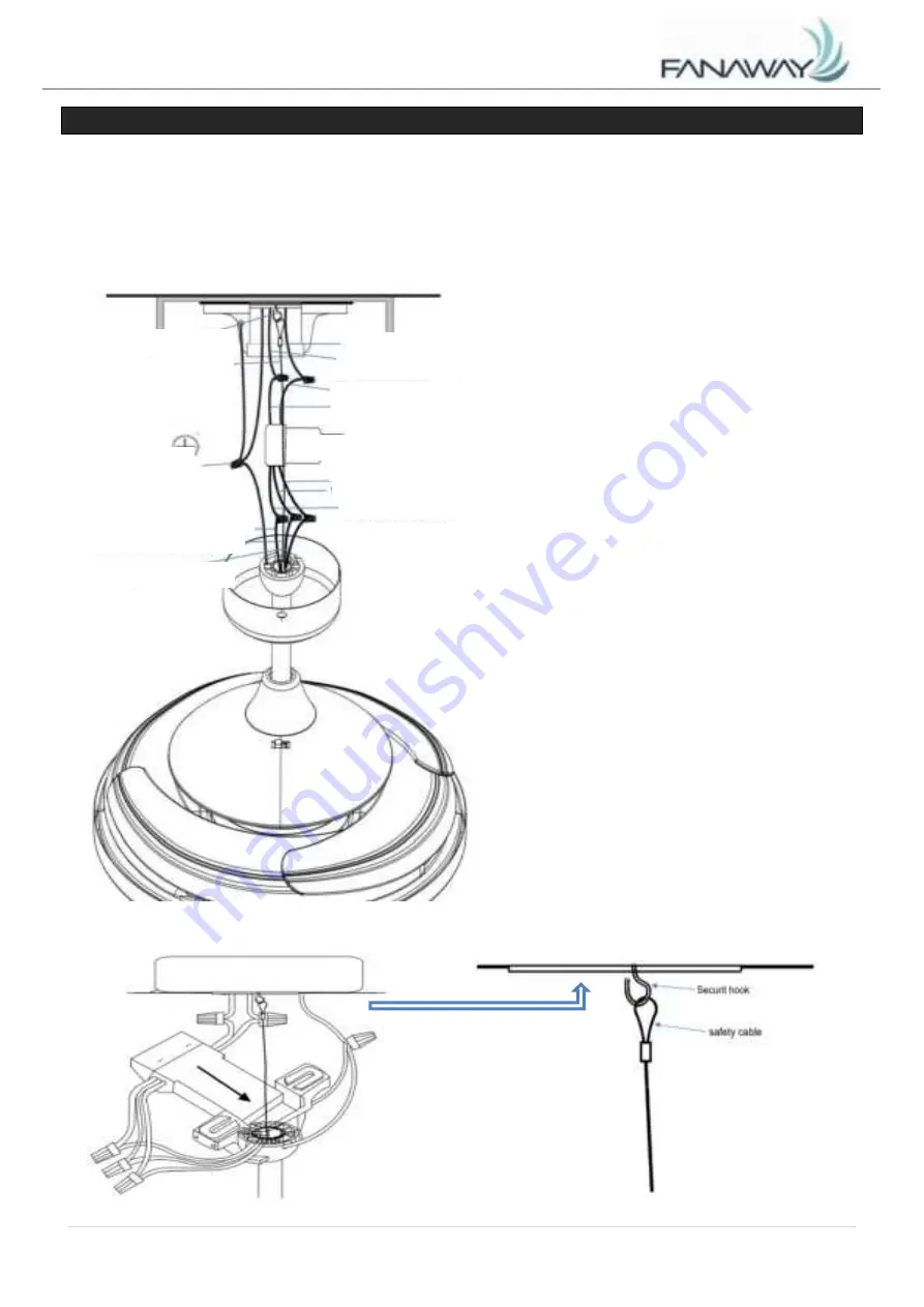
DIAGRAMA DE CABLEADO ELÉCTRICO


ADVERTENCIA: 

Para evitar cualquier posible descarga eléctrica, asegúrese de haber desconectado la 

alimentación eléctrica en el panel de circuito general. 
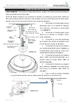
Siga los pasos que aparecen a continuación para conectar el ventilador al cableado de su casa. Use las 
tuercas  de  conexión  de  cable  que  se  suministran  con  su  ventilador.  Fije  los  conectores  con  cinta 
eléctrica. Asegúrese de que no haya hilos de cables sueltos o conexiones flojas. 

1. 

Conecte  el  cable  vivo  del  suministro 

eléctrico del hogar (negro) al cable de entrada 
del receptor (negro, AC IN L) como se muestra 
en la 

Fig. 11.


2. 

Conecte 

el  cable 

neutro 

del 

suministro eléctrico del hogar (blanco) al cable 
de entrada del receptor (blanco, CA EN N).   

3. 

Conecte el cable a tierra de la casa al 

cable a tierra del soporte del ventilador (verde) 
y al cable a tierra del cuerpo del ventilador.   

4. 

Conecte  el  cable  de  salida  del 

receptor (negro AL MOTOR VIVO) al cable de 
entrada  vivo  del  motor  (negro,  AL  MOTOR 
VIVO). 

5. 

Conecte  el  cable  de  salida  del 

receptor  (blanco,  AL  MOTOR  NEUTRO)  al 
cable  de  entrada  neutro  del  motor (blanco,  AL 
MOTOR NEUTRO). 

6. 

Conecte  el  cable  de  salida  del 

receptor  (azul,  PARA  LA  LUZ)  al  cable  de 
entrada vivo de la luz del ventilador (azul, PARA 
LA LUZ) 

7. 

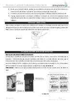
Tire del cable de seguridad de metal 

situado en el gancho de seguridad, ajuste el cable de seguridad (Fig.11a y Fig.11b)   

Fig. 11a


Fig. 11b


Gancho de seguridad


Cable de seguridad 

de metal


CONEXIÓ

N A 

TIERRA


Azul (Para la LUZ)


Blanco (Al motor N)


Negro (Al motor L)


Receptor


Negro L (Vivo)


Blanco N (Neutro)


Negro (CA EN L)


Blanco (CA EN 

N)

Negro (Al motor L)


Blanco (Al motor N)


Azul (Para la LUZ)


Summary of Contents for 212923

Page 1: ...port beaconlighting us www beaconlighting us US Patent 8317470 8807938 8790085 9255584 8851841 V1 0 06 2021 FANAWAY VEIL CEILING FAN INSTALLATION OPERATION MAINTENANCE WARRANTY INFORMATION CAUTION REA...

Page 2: ...ING To reduce the risk of personal injury do not bend the blade brackets when installing the blade brackets balancing the blades or cleaning the fan Do not insert foreign objects in between rotating f...

Page 3: ...ing fan has been damaged during transport Do not operate install any product which appears damaged in any way Return the complete product to the place of purchase for inspection repair or replacement...

Page 4: ...the outlet box A not included This fan hanging system supports a maximum 15 degree angled ceiling installation Fig 4 NOTE If you are installing the ceiling fan on a sloped ceiling you may need a longe...

Page 5: ...o reassemble later Fig 6 1 Fig 6 1 2 Loosen the set screws 11 on the down rod coupling housing 8 Fig 6 2 3 Carefully feed the fan wires 1 up through the down rod 6 Fig 6 3 4 Assemble the down rod 6 in...

Page 6: ...e light kit counterclockwise until the slot screws are firmly at the end of the slots 2 3 Secure screw 1 to the light kit bracket Tighten all three screws Do not over tighten Fig 7 6 Insert the decora...

Page 7: ...the decorative drops 6 to the light kit HANGING THE FAN Pass the power supply wires C from the ceiling outlet box B through the center of the ceiling mounting bracket D Install the ceiling mounting br...

Page 8: ...2 Connect the household neutral supply wire white to the receiver input wire white AC IN N 3 Connect the household ground wire to the fan bracket ground wire green and fan body ground wire 4 Connect t...

Page 9: ...screws provided USING YOUR CEILING FAN SETTING DIP SWITCHES When two or more fans are located near each other you may desire to have the receiver transmitter for each fan set to a different code so t...

Page 10: ...ed LED indicator on the top of the transmitter will flash when the buttons are active BUTTONS ON THE REMOTE HI Press the button to set fan running at High speed MED Press the button to set fan running...

Page 11: ...operation due to the fact that they are mounted on a rubber grommet If the fan was mounted rigidly to the ceiling it would cause excessive vibration Movement of a few centimetres is quite acceptable...

Page 12: ...y of an electrical shock 3 Ensure that the fan does not come in contact with any organic solvents or cleaners 4 To clean the fan blade wipe with only a damp clean cloth with NO organic solvents or cle...

Page 13: ...o de que se produzcan fuegos o descargas el ctricas no use este ventilador con dispositivos de control de velocidad de estado s lido 4 ADVERTENCIA Para disminuir el riesgo de que se produzcan lesiones...

Page 14: ...con las instrucciones puede causar interferencia da ina con las comunicaciones de radio 9 PRECAUCI N Para reducir el riesgo de descarga el ctrica desconecte el circuito de suministro el ctrico del ven...

Page 15: ...No ponga en funcionamiento ni instale ning n producto que parezca tener alg n tipo de da o Regrese el producto completo al lugar donde lo adquiri para que lo examinen reparen o reemplacen Examine e id...

Page 16: ...no incluida Este sistema de cuelgue de ventilador soporta un ngulo m ximo de 15 grados en la instalaci n de techo Fig 4 NOTA Si va a instalar el ventilador en un techo inclinado es posible que necesi...

Page 17: ...ijaci n 11 de la caja de acoplamiento de la varilla descendente 8 Fig 6 2 3 Pase con cuidado los cables del ventilador 1 hacia arriba a trav s de la varilla descendente 6 Fig 6 3 4 Monte la varilla de...

Page 18: ...e 6 y aseg relos ajustando los tornillos de fijaci n 4 Fig 6 5 y Fig 6 6 INSTALACI N DEL VENTILADOR INSTALACI N DEL KIT DE ILUMINACI N Fig 7 y 8 1 Afloje el tornillo 1 del soporte del ventilador Ponga...

Page 19: ...go de luces C MO COLGAR EL VENTILADOR Pase los cables de alimentaci n el ctrica C de la caja de salida del techo B a trav s del centro del soporte de armado en el techo D Instale el soporte de armado...

Page 20: ...del hogar blanco al cable de entrada del receptor blanco CA EN N 3 Conecte el cable a tierra de la casa al cable a tierra del soporte del ventilador verde y al cable a tierra del cuerpo del ventilado...

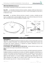
Page 21: ...de colgado con los tornillos suministrados USO DE SU VENTILADOR DE TECHO CONFIGURACI N DE LOS INTERRUPTORES DIP Cuando uno o m s ventiladores se encuentran a poca distancia uno del otro podr a ser co...

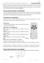
Page 22: ...on los botones y la funci n de cada uno de ellos Indicador LED El indicador LED rojo situado en la parte superior del transmisor parpadea cuando los botones est n activos BOTONES DEL CONTROL REMOTO AL...

Page 23: ...dor se mont en el techo de forma r gida esto podr a causar una vibraci n excesiva Un movimiento de unos cent metros es aceptable y NO indica problema alguno C MO REDUCIR EL BAMBOLEO DEL VENTILADOR Ver...

Page 24: ...permita que el ventilador entre en contacto con disolventes org nicos ni con productos de limpieza 4 Limpie las aspas solo con un pa o h medo y NO utilice disolventes org nicos ni productos de limpiez...

Page 25: ...ltez un lectricien qualifi en cas de doute 3 AVERTISSEMENT Pour r duire les risques d incendie ou de choc lectrique n utilisez pas ce ventilateur avec un dispositif de contr le de la vitesse semi cond...

Page 26: ...orm ment aux instructions il peut causer des interf rences nuisibles aux communications radio 9 ATTENTION Pour r duire le risque de choc lectrique d branchez le circuit d alimentation lectrique du ven...

Page 27: ...ndant le transport N utilisez n installez aucun produit qui semble endommag de quelque mani re que ce soit Renvoyez le produit complet au lieu d achat pour le faire inspecter r parer ou remplacer Exam...

Page 28: ...teur est adapt pour une installation sur un plafond inclin de 15 degr s au maximum Sch ma 4 REMARQUE Si vous installez le ventilateur de plafond sur un plafond inclin vous aurez peut tre besoin d une...

Page 29: ...nt et en alignant les trous du bo tier de raccord de la tige de suspension avec les trous de la tige de suspension puis ins rez la goupille d attelage 9 et fixez la avec le clip de verrouillage 10 Sch...

Page 30: ...en serrant les vis de r glage 4 Sch ma 6 5 et sch ma 6 6 INSTALLATION DU VENTILATEUR INSTALLATION DU KIT D CLAIRAGE sch mas 7 et 8 1 Desserrez la vis 1 du support du ventilateur Alignez les deux vis f...

Page 31: ...SPENSION DU VENTILATEUR Faites passer les fils d alimentation C du bo tier de sortie du plafond B par le centre du support de montage au plafond D Installez le support de montage au plafond D sur le b...

Page 32: ...fil de terre domestique au fil de terre de la fixation du ventilateur vert et au fil de terre du bo tier du ventilateur 4 Connectez le fil de sortie du r cepteur noir VERS LE MOTEUR SOUS TENSION au fi...

Page 33: ...e au support de suspension l aide des vis fournies UTILISATION DE VOTRE VENTILATEUR DE PLAFOND INSTALLATION DES COMMUTATEURS DIP Lorsque deux ventilateurs ou plus sont situ s proches l un de l autre v...

Page 34: ...et la fonction de chaque bouton Indicateur LED L indicateur LED rouge situ sur le dessus de la t l commande clignote lorsque les boutons sont actifs BOUTONS DE LA T L COMMANDE FORT Appuyez sur ce bou...

Page 35: ...e mani re rigide au plafond cela provoquerait des vibrations excessives Un mouvement de quelques centim tres est tout fait acceptable et NE sugg re AUCUN probl me POUR R DUIRE LES TREMBLEMENTS DU VENT...

Page 36: ...le raccord n entre pas en contact avec des solvants organiques ou des produits de nettoyage 4 Pour nettoyer les pales du ventilateur essuyez les uniquement avec un chiffon propre et humide SANS solvan...

Reviews: