background image

INSTALLATION AND ASSEMBLY

CAUTION: Before installing the fan make sure you have turned OFF the electricity supply.

SELECTING A LOCATION: 
1. Choose a location for mounting the fan where the blades will have at least 2.1 metres of 
clearance from the floor. 
2. Make sure that the installation site will not allow the rotating fan blades to come into 
contact with any object and that there is enough space from the blade tip to the wall or 
ceiling. Please note that insufficient clearance distances might cause wobbling and the 
bigger this clearance is the better the airflow from your fan will be.
3. This product can be installed in a position where it is covered or enclosed al fresco areas 
and there is a minimum clearance of 1.50 m from the blade tip to all edges of the roof or 
positions where could be exposed to water, moisture or other dangerous external elements.
4. Secure the hanging bracket to the ceiling joist or suitable structure that is capable of 
carrying a load of at least 45 kg, with the two long fixing screws provided. Ensure that at 
least 30mm of the screw is threaded into the support.

The fixing screws included are designed for use when ceiling fan is secured onto timber 
joists. For all other surfaces, additional and suitable fixing screws for that surface will need 
to be purchased.

3

1

2

3

4

5

6

7

1

X1

X1

X1

X3

X1

X1

X1

2

3

4

5

6

7

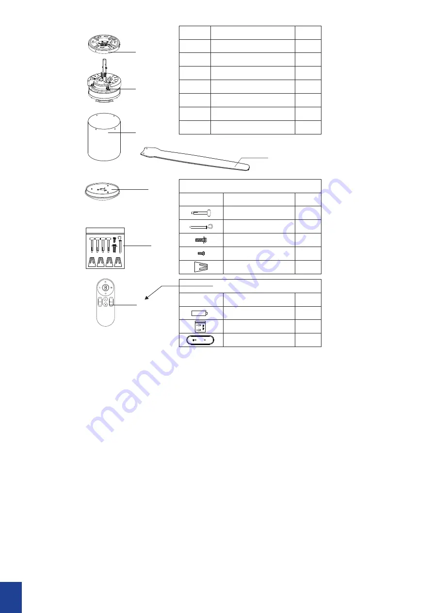
Top cover

Bracket ,Canopy

Motor

Blade

lamp plate or Base plate 

Serial number

name

Pieces

Screw bag

Emitter ,screw bag

pattern

X4

X1

X1

X1

X4

screw package details

Expansion Screws

J Hook

Screw

Screw

Wiring cap

name

Pieces

X2

X1

X1

Remote control accessories

Battery

Screw bag

Emitter holder

pattern

name

Pieces

Summary of Contents for CFFCST2LWHSMR

Page 1: ...Studio DC DC Installation Manual...

Page 2: ...the wall or ceiling Please note that insufficient clearance distances might cause wobbling and the bigger this clearance is the better the airflow from your fan will be 8 DO NOT install this product o...

Page 3: ...hink batteries might have been swallowed or placed inside any part of the body seek immediate medical attention Call the Poisons Information Centre on 13 11 26 or go to a hospital emergency room Do no...

Page 4: ...om the blade tip to all edges of the roof or positions where could be exposed to water moisture or other dangerous external elements 4 Secure the hanging bracket to the ceiling joist or suitable struc...

Page 5: ...Switch E L N C 2 1 Power Supply Live Wire Brown Power Supply Neutral Wire Blue Ground Wire Yellow Green E L N L in L out Double pole disconnection switch or 2 pin plug Wall Switch Power Supply Live W...

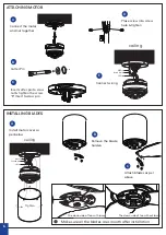
Page 6: ...n the rubber nut with the bracket Use screws to fix the parts together Complete Use the bracket as a guide to mark required screw holes Drill Holes place expanding screws into the holes Place bracket...

Page 7: ...ert to cross pin C Place screw into screw hole tighten D Connect wiring E Install motor cover as per below A Remove the blade holders B Attach blades as per above C Ground wire N Wire L Wire ceiling T...

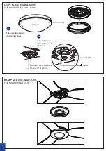
Page 8: ...w off as photo S crew off Loosen L oosen Finish LIGHT PLATE INSTALLATION FOR FAN WITH LED LIGHT ONLY Seperate lamp plate and lamp shade A Loosen 2 screws remove 1 screw as picvtured B BASE PLATE INSTA...

Page 9: ...ion Light Diffuser Installation Screw hole alignment scr ew Tighten Rotate into position and tighten the screw A Tighten screws B Insert wire into lamp plate C Align the lock points A Gently twist dif...

Page 10: ...NDER WARRANTY but a little care and maintenance can reduce or prevent this problem REMOTE CONTROL SETTINGS AND OPERATION FOR DC FANS NOTE The Hand Held Remote Control System is equipped with a learnin...

Page 11: ...more fans you should manually isolate power to Fan B while completing the pairing process on Fan A If power is not isolated to one of the fans when the power is restored at the fuse box then both rece...

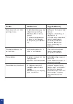
Page 12: ...and wiring on premises Fan keeps beeping but will not start Loose wire connections or plugs to fan receiver Check wire connections and ensure plugs are positively connected Fan wobbles A Screws on do...

Page 13: ...Number Rated Voltage Motor Consumption Rated Light Power CFFCST2WHSMR 220 240Vac Max 45 W DC Motor N A CFFCST2LWHSMR 220 240Vac Max 45 W DC Motor Max 18W LED CFFCST2WHW 220 240Vac Max 45 W DC Motor N...

Page 14: ......

Reviews: