


INSTALLATION AND ASSEMBLY
CAUTION: Before installing the fan make sure you have turned OFF the electricity supply.
SELECTING A LOCATION:
1. Choose a location for mounting the fan where the blades will have at least 2.1 metres of
clearance from the floor.
2. Make sure that the installation site will not allow the rotating fan blades to come into
contact with any object and that there is enough space from the blade tip to the wall or
ceiling. Please note that insufficient clearance distances might cause wobbling and the
bigger this clearance is the better the airflow from your fan will be.
3. This product can be installed in a position where it is covered or enclosed al fresco areas
and there is a minimum clearance of 1.50 m from the blade tip to all edges of the roof or
positions where could be exposed to water, moisture or other dangerous external elements.
4. Secure the hanging bracket to the ceiling joist or suitable structure that is capable of
carrying a load of at least 45 kg, with the two long fixing screws provided. Ensure that at
least 30mm of the screw is threaded into the support.
The fixing screws included are designed for use when ceiling fan is secured onto timber
joists. For all other surfaces, additional and suitable fixing screws for that surface will need
to be purchased.
3
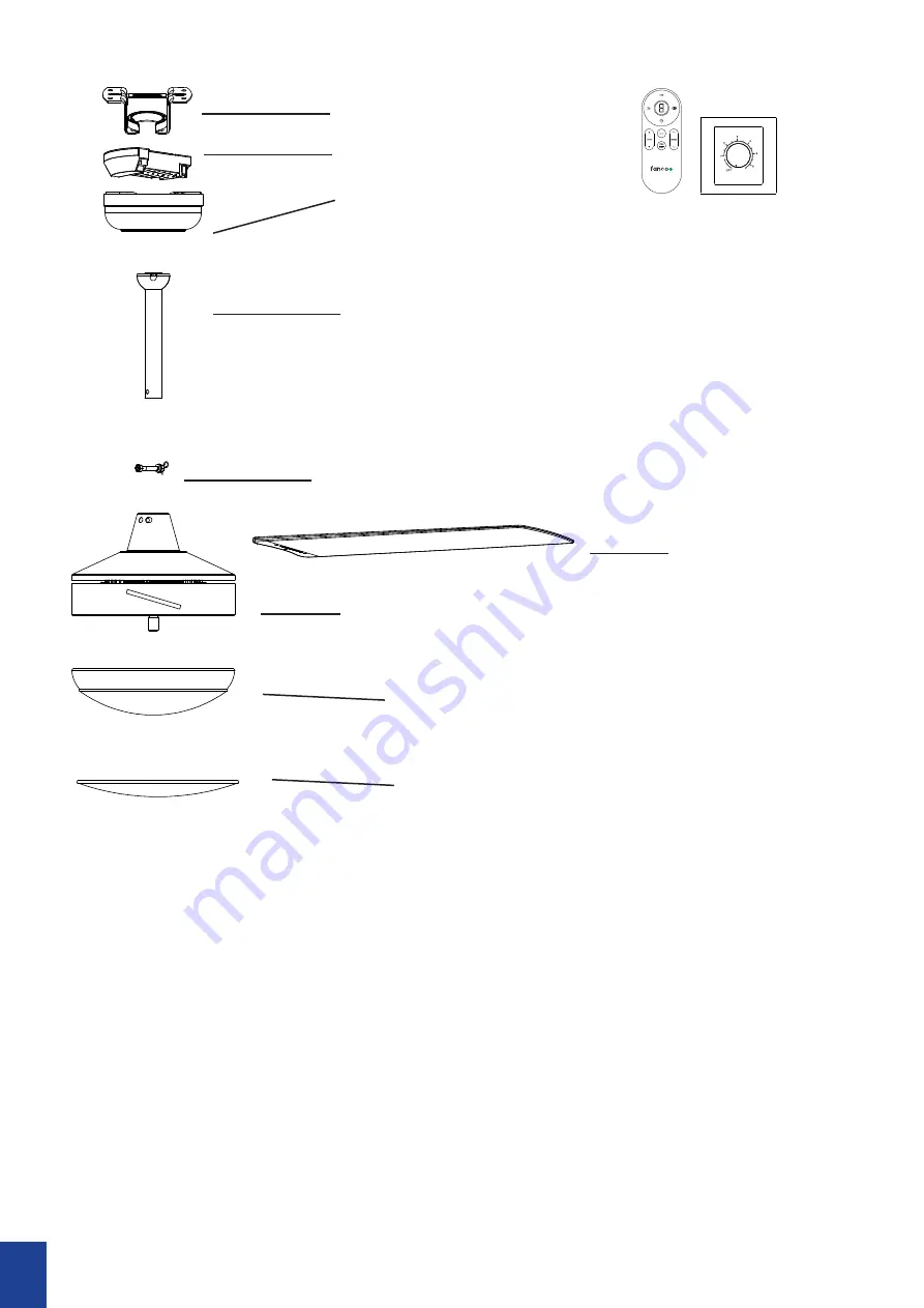
Canopy
Downrod with Ball Joint
Blade
Light Kit (with Light Models ONLY)
PARTS INCLUDED
No Light Cap
Hanging Bracket
Receiver
Cotter Pin & Cross Pin
Motor
Remote or Wall Control
Summary of Contents for Eco Silent Deluxe DC
Page 1: ...Eco Silent Deluxe DC DC Installation Manual...
Page 16: ......


