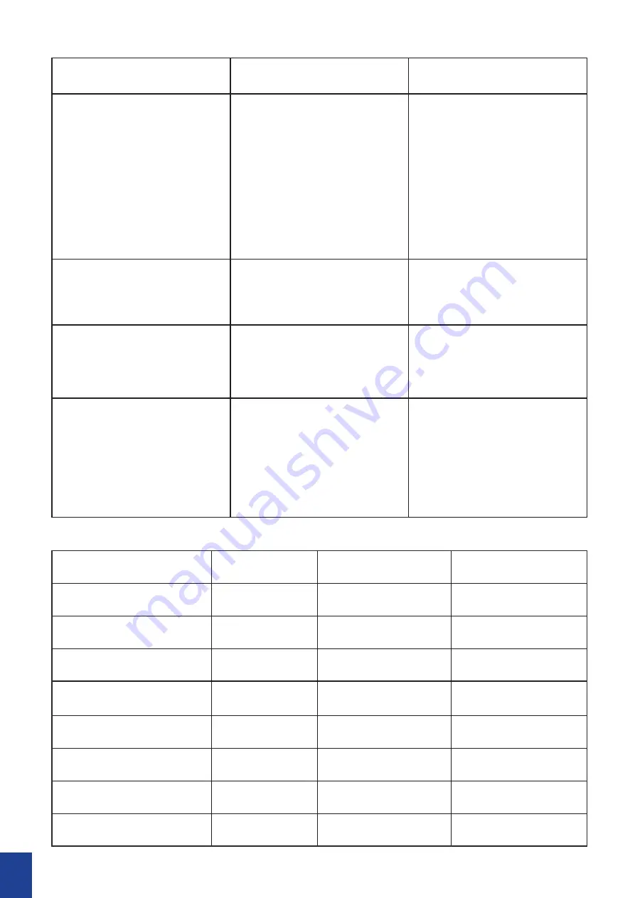
background image

Trouble

Possible Cause

Suggested Remedy

Fans does not start after 
pairing process

A) Remote and receiver are 
not paired successfully
B) Battery flat in remote 
control
C) Loose wire connections 
or plugs to fan/receiver
D) No power goes into the 
fan

A) Re-pair the receiver and 
remote
B) Replace the battery in 
remote control
C) Check wire connections 
and ensure plugs are 
positively connected
D) Check RCD/Switch 
board and wiring on 
premises

Fan keeps beeping, but 
will not start.

Loose wire connections or 
plugs to fan/receiver

Check wire connections 
and ensure plugs are 
positively connected

Fan wobbles.

A) Screws on down rod are 
not tightened
B) Blades are not balanced

A) Retighten the screws on 
down rod
B) Use the balancing kit to 
balance the blades.

Fan makes clicking sound.

A) Coupling cover does 
not sit securely on motor 
housing
B) Rubber ring on coupling 
cover is removed

A) Adjust coupling cover 
and ensure it sits properly 
on the motor housing
B) Check couple cover and 
ensure there’s a rubber 
ring on the top of the 
cover.

Model Number

Rated Voltage

Motor Consumption Rated Light Power

W- CFFCSAMB-B5NA

220-240Vac

Max. 55 W DC Motor N/A

W- CFFCSAMB-B5WA

220-240Vac

Max. 55 W DC Motor N/A

W- CFFCSAMB-B5TK

220-240Vac

Max. 55 W DC Motor N/A

W- CFFCSAMB-B5WH

220-240Vac

Max. 55 W DC Motor N/A

W- CFFCSAMB-B6NA

220-240Vac

Max. 55 W DC Motor N/A

W- CFFCSAMB-B6WA

220-240Vac

Max. 55 W DC Motor N/A

W- CFFCSAMB-B6TK

220-240Vac

Max. 55 W DC Motor

N/A

W- CFFCSAMB-B6WH

220-240Vac

Max. 55 W DC Motor N/A

10

Summary of Contents for Sanctuary DC W-CFFCSAMB-B5NA

Page 1: ...Sanctuary DC DC Installation Manual...

Page 2: ...ceiling Please note that insufficient clearance distances might cause wobbling and the bigger this clearance is the better the airflow from your fan will be 8 This product can be installed in a positi...

Page 3: ...d keep it away from children If you think batteries might have been swallowed or placed inside any part of the body seek immediate medical attention Call the Poisons Information Centre on 13 11 26 or...

Page 4: ...imum clearance of 1 50 m from the blade tip to all edges of the roof or positions where could be exposed to water moisture or other dangerous external elements 4 Secure the hanging bracket to the ceil...

Page 5: ...tenna Wire Black Wire Power Supply Livewire Power Supply Neutral Wire Ground Wire C 1 2 Wall Switch Double pole disconnection switch or 2 pin plug Brown Blue Yellow Green WIRING DIAGRAM 4 ELECTRICAL C...

Page 6: ...the main motor wire plug up through the inside of the downrod then insert the downrod into the motor bush Gently push the cross pin through the holes aligned with the base of the motor bush and downr...

Page 7: ...remove rubber gasket on top of the coupling cover 4 Put the decorative ring and canopy through the down rod 5 Place the hanging ball on top of the down rod and secure it with the ball pin and two scre...

Page 8: ...er receiver and the fan as electrical wiring diagram IMPORTANT The fan must be earthed Double pole disconnection switch and wall switch must be connected 9 Place the canopy over the bracket align the...

Page 9: ...duce or prevent this problem REMOTE CONTROL SETTINGS AND OPERATION FOR DC FANS NOTE The Hand Held Remote Control System is equipped with a learning frequency function which has code combinations to pr...

Page 10: ...s When installing two or more fans you should manually isolate power to Fan B while completing the pairing process on Fan A If power is not isolated to one of the fans when the power is restored at th...

Page 11: ...lades are not balanced A Retighten the screws on down rod B Use the balancing kit to balance the blades Fan makes clicking sound A Coupling cover does not sit securely on motor housing B Rubber ring o...

Page 12: ......

Reviews: