Gnd
13
g
If the control signal or power supply is interrupted, the IMS can control the air inlet position independently. This
may be a calculated position or the preferential position (predefined). This predefined position can be set (see
page 12).
No control signal (10-0V / 0-10V)
When the control signal is interrupted, the air inlet will open completely (with a 10-0 V control signal) or close
completely (with a 0-10 V control signal).
No control signal (communication)
If the IMS is included in an I/O network and communication is interrupted, then the
A4
alarm will appear after 6
minutes. Independent regulation will occur if a temperature sensor is connected. The regulation's basic principles
are:
The current temperature becomes the set point temperature.
The current valve position becomes the minimal valve position or - if lower - the predefined valve position.
The intelligent module will calculate the air intake position itself based on the temperature measurement and the
settings. In this case, an
L
will be displayed on the display of the circuit board by pressing the pushbutton. If no
temperature sensor is connected, the predefined position will be sought. An
L
appears on the display.
Loss of power (power failure)
When using an external emergency power supply (UPS) the 230 V AC will not be interrupted. The UPS must,
however, be equipped with a Power Fail (PF) output (normally open contact) that connects the PF input on the
IMS whenever regular mains power is interrupted. The IMS will send the actuator to the preferential position. An
A3
will be shown on the display.
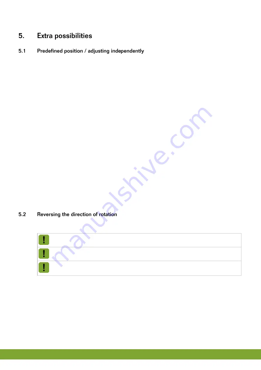
The direction of rotation of the connected actuator can be reversed. This possibility is used whenever the
connection has been made in the opposite direction.
Always restore the factory settings before changing the direction of rotation.
Don’t switch the CPS wires connected to the circuit board. This will damage the CPS.
Adjust the CLOSE cam disc of a LM motor against the upper side of the CLOSE limiting switch.
Adjust the OPEN cam disc of a LM motor against the underside of the Open limiting switch.
LM.125 / .250 single phase
To reverse the direction of rotation, perform the following steps:
1. Restore the factory settings (see page 14).
2. Switch off the power from the IMS.
3. Set DIP 8 to OFF (= inverse direction of rotation).
4. At the LM.125 / LM.250 change over the
MOTOR OPEN
and
MOTOR CLOSE
connection (terminal 1 and 2)
of the motor connection terminal.
Summary of Contents for IMS
Page 1: ...G N D Gnd...
Page 20: ...Gnd 17 g...
Page 21: ...Gnd 18 g...
Page 29: ...gNd 5 n...
Page 41: ...gNd 17 n...
Page 42: ...gNd 18 n...
Page 62: ...gnD 17 d...
Page 63: ...gnD 18 d...

