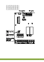
Gnd
12
g
Make sure the close position is adjusted.
For 10-0V or 0-10V control, you should ensure that the control computer's analogue output sends out
99%. Recommendable is 0.5V if a 10-0V voltage control is used. (For an I/O network control system
this is not important.)
1. Set the manual switch to the
OPEN
position (
) and allow the air inlet to go to the desired position.
2. Set the manual switch to an OFF (
O
) position.
3. Press the pushbutton until the number
2
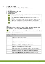
appears in the display and then release the pushbutton. The IMS is
now in the 99% adjustment mode. After releasing the pushbutton, a dash will appear in the display.
4. The dash must be in the middle. If not, the stroke is to short. Open the motor a bit more or change the close
adjustment, but make sure the inlet open position is correct.
5. Press the pushbutton to confirm the setting. The letter
O
now appears in the display. This means that the
adjustment was successful.
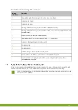
Is there something other than
O
in the display? Then the adjustment was not successful. If no
improvement occurs, then repeat the entire procedure starting with adjusting the close position.
Factory setting = 50%. If this is the proper position for you, you don't have to perform the following
steps.
1. Set the air inlet with the manual operation switch to the position that should be assumed if mains power is
interrupted.
2. Set the manual switch to an OFF (
O
) position.
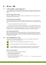
3. Press the pushbutton until the number
3
appears in the display and then release the pushbutton.
4. Press the pushbutton to confirm the setting. The letter
P
now appears in the display. This means that the
adjustment was successful.
After adjustment, set the operating switch to Automatic (
AUT
) so that normal functioning is possible.
Summary of Contents for IMS
Page 1: ...G N D Gnd...
Page 20: ...Gnd 17 g...
Page 21: ...Gnd 18 g...
Page 29: ...gNd 5 n...
Page 41: ...gNd 17 n...
Page 42: ...gNd 18 n...
Page 62: ...gnD 17 d...
Page 63: ...gnD 18 d...


