background image

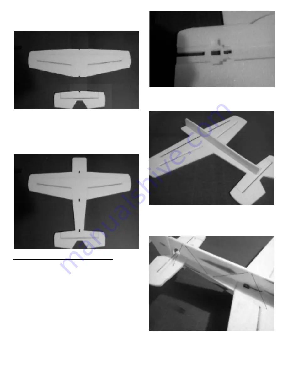
Hinge the ailerons to the wing and the elevator to the
horizontal stabilizer. (A Welders glue hinge
instructional video is on the web site.)

Glue together the horizontal pieces; nose, wing, rear
fuselage and horizontal tail. Note: The wing spar goes
on the bottom and the aileron and elevator hinges go
on top.

Lower fuselage to horizontal – Assembly:

If using a stick mount, cut a slot in the horizontal nose
piece and glue the mount in place. For a firewall plate
wait until the airframe is built before installing. Set
motor mount with NO right or down thrust. It is not
required.

If installing a single aileron servo then cut a pocket
for it now in the nose piece. Lay the vertical pieces on
the horizontal assembly to mark and cut clearance
pockets for the aileron servo.

Glue the lower vertical fuselage pieces to the
horizontal assembly making sure it is square.

Now is the time to add carbon bracing to the tail. Cut 
the 1mm carbon rod into 2 – 3.5” pieces and 6 – 5.25” 
pieces. Glue them per the picture with hotglue.

2

Summary of Contents for 32” Yak-55

Page 1: ... and kit to us for a refund By building the kit and using the batteries you accept full responsibility for the safety of these batteries Recommended building methods and glues Much of the construction of this model is done by laying the parts on a flat table It is strongly recommended that you put wax paper down on the surface first so any excess glue doesn t soak through the foam and glue the par...

Page 2: ...ece and glue the mount in place For a firewall plate wait until the airframe is built before installing Set motor mount with NO right or down thrust It is not required If installing a single aileron servo then cut a pocket for it now in the nose piece Lay the vertical pieces on the horizontal assembly to mark and cut clearance pockets for the aileron servo Glue the lower vertical fuselage pieces t...

Page 3: ... to slot the control horn locations in the ailerons elevator and rudder Glue the horns in place With all the surfaces set to zero measure the distance between servo arm holes and control horn holes Cut a piece of 1 5mm carbon rod for each push rod to the measured lengths Cut a 1 5 long piece of 1 32 wire and make a z bend on one end Slide a 1 length of heat shrink over each end of the carbon rod a...

Page 4: ...e model proper balance Adjust the battery location back and forth to suit your flying style Use your computer radio to set the final sub trims exponential and dual rates Double check the control directions before your first flight With proper CG the plane should fly nearly the same upright or upside down Good pilots experiment with various battery locations until the CG feels just right For indoor...

Reviews: