background image

- 1 -

STR-4D

Roller blind controller

for 12/24 V DC

The STR-4D controller is designed to control roller blinds (

���

����

) or other objects (e.g. gates) that are driven with DC elec-

tric motor supplied by 12 V or 24 V with momentary switch (eg. 

bell).

The controller can operate as a stand-alone device (for opening/

closing of a single roller blind), but it is also possible to combine 

controllers into groups to control multiple roller blinds. Roller 

blind motor starts after momentary passing of the "+" signal to 

one of the control inputs. The motor activates for the user-pro-

grammed time that allows to fully lift or lower the roller blind.

Roller blind can be stopped on the user-selected level (incomple-

te opening or closing of the roller blind).

Purpose

Functioning

F&F Filipowski sp. j.

Konstantynowska 79/81, 95-200 Pabianice, POLAND

phone/fax (+48 42) 215 23 83 / (+48 42) 227 09 71

www.fif.com.pl; e-mail: biuro@fif.com.pl

Do not dispose of this device in the trash along with other waste!  

According 

to the Law on Waste, electro coming from households free of charge and 

can  give  any  amount  to  up  to  that  end  point  of  collec� on,  as  well  as  to  sto-

re the occasion of the purchase of new equipment (in accordance with the 

principle of old-for-new, regardless of brand). Electro thrown in the trash or 

abandoned in nature, pose a threat to the environment and human health.

Summary of Contents for STR-4D

Page 1: ...that allows to fully lift or lower the roller blind Roller blind can be stopped on the user selected level incomple te opening or closing of the roller blind Purpose Functioning F F Filipowski sp j Konstantynowska 79 81 95 200 Pabianice POLAND phone fax 48 42 215 23 83 48 42 227 09 71 www fif com pl e mail biuro fif com pl Do not dispose of this device in the trash along with other waste According...

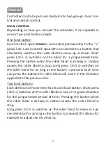
Page 2: ...eady in motion causes the roller blind to stop Long press 0 5 s switches on the roller blind for as long as the button is pressed Each time you press the button the roller blind will move in the direction opposite to the previous one Two local buttons Each direction of movement has its own local button Short press 0 5 s switches on the roller blind to move in a given direction for the programmed p...

Page 3: ...ove only in the de sired direction Roller blind will stop only after a preset time or by pressing any of the local control buttons If during the execution of one center control command another one is issued with the instruction to move in the opposite direc tion the roller blind will stop at first and after 1 5 s will then start to move in the opposite direction Time of roller blind activation can...

Page 4: ...en preparing the installation powered with 12 24 V voltage it is necessary to provide a power source with sufficient current capacity to supply all receivers Too small power supply may lead to improper operation of motors and roller shutter controllers Additionally vol tage drops on cables mainly power cables should be taken into account and if necessary the diameter of the cables should be increa...

Page 5: ...ime in non volatile memory and then exit the programming mode which is indi cated by the constant U LED light Test run 1 Place the blind in the outmost top or bottom position 2 Press and hold for approx 4s the button until the green U LED will begin to flash slowly The controller is now ready for programming 3 Short press the local control or button in the oppo site direction to the current positi...

Page 6: ...xit the learning mode The controller is designed to measure time span shorter than 15 min Attempting to set the controller for longer span will result in exit from the learning mode The controller learning mode can be started only when the roller blind motor is turned off Operation with factory settings activation time set to 30 seconds is indicated in standby mode by short 0 1 s blinking of U LED...

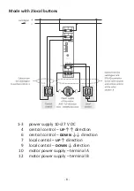
Page 7: ...tton 1 3 power supply 10 27 V DC 4 central control direction 6 central control direction 7 local control direction 9 local control direction 10 motor power supply terminal A 12 motor power supply terminal B Connection diagram ...

Page 8: ... local buttons 1 3 power supply 10 27 V DC 4 central control direction 6 central control direction 7 local control direction 9 local control direction 10 motor power supply terminal A 12 motor power supply terminal B ...

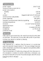
Page 9: ... products are covered by a 24 month warranty from the date of purchase The warranty is only valid with proof of purchase Contact your dealer or contact us directly F F Filipowski sp j declares that the device is in conformity with the essential requirements of The Low Voltage Directive LVD 2014 35 EU and the Electromagnetic Compatibility EMC Directive 2014 30 UE The CE Declaration of Conformity al...

Page 10: ......

Reviews: