background image

Hardware Documentation efus™A9X+ efus™A9Xr2

 | 11

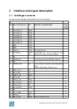
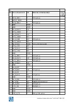
J1

Pin Use on base board

I/O

Remarks; onboard pullups

1.12-> 

1.20  

change

126 I2S_DIN

O5*

127 LCD_G5

O5*

128 GND

PWR

129 GND

PWR

130 I2C_C_DAT

I/O

4.7k pull up

131 LCD_B0

O5*

132 I2C_C_CLK

I/O

4.7k pull up

133 LCD_B1

O5*

134 DVI_DDC_VOUT

PWR

3.3V output for DDC

135 LCD_B2

O5*

136 GND

PWR

137 LCD_B3

O5*

138 NC

LVDS_TX2_DP  available  on  a  special  version  with  minimum 
order quantity

X

139 LCD_B4

O5*

140 NC

LVDS_TX2_DN  available  on  a  special  version  with  minimum 
order quantity

X

141 LCD_B5

O5*

142 NC

LVDS_TX1_DP  available  on  a  special  version  with  minimum 
order quantity

X

143 GND

PWR

144 NC

LVDS_TX1_DN  available  on  a  special  version  with  minimum 
order quantity

X

145 LCD_DE

O5*

146 NC

LVDS_TX0_DP  available  on  a  special  version  with  minimum 
order quantity

X

147 GND

PWR

148 NC

LVDS_TX0_DN  available  on  a  special  version  with  minimum 
order quantity

X

149 VLCD_ON

O5*

150 NC

LVDS_CLK_DP  available  on  a  special  version  with  minimum 
order quantity

X

151 I2C_A_DAT

I/O*

4.7k pull up

152 NC

LVDS_CLK_DN  available  on  a  special  version  with  minimum 
order quantity

X

153 I2C_A_IRQ

I*

100k pull up

154 NC

LVDS_TX3_DP  available  on  a  special  version  with  minimum 
order quantity

X

155 I2C_A_CLK

O5*

4.7k pull up

Summary of Contents for efus A9X

Page 1: ...ion efus A9X for HW Revision 1 12 and 1 20 and 1 30 efus A9Xr2 for HW Revision 1 00 Version 260 2022 10 20 F S Elektronik Systeme GmbH Untere Waldpl tze 23 D 70569 Stuttgart Fon 49 0 711 123722 0 Fax...

Page 2: ...r efusA9Xr2 is Version 1 00 The only difference between these two modules is their Gbit Ethernet PHY s efus A9X Qualcomm Atheros AR8035 efus A9Xr2 Realtek RTL8211F D ESD Requirements All F S hardware...

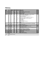
Page 3: ...me PU Add eMMC Add WLAN BT Add additional UART options Remove SATA Add KW 06 09 16 1 0 All A 17 0 Added information on ESD Requirements Packaging and Matrix Code Sticker JG 19 10 16 1 1 All A 0 Add U...

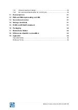
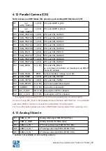
Page 4: ...evice 15 4 3 CAN Bus 15 4 4 SD MMC card 16 4 5 SPI 17 4 6 I2C 18 4 7 Serial ports 19 4 8 I2S audio codec interface 19 4 9 Ethernet 20 4 10 PCIe 21 4 11 RGB LCD 22 4 12 Parallel Camera CSI 23 4 13 Anal...

Page 5: ...ristics for 3 3V IO pins 30 11 Review service 31 12 ESD and EMI implementing on COM 31 13 Second source rules 31 14 Storage conditions 31 15 ROHS and REACH statement 31 16 Packaging 32 17 Matrix Code...

Page 6: ...ector DDR3 SLC NAND Flash up to 1GB or Quad SPI eMMC up to 32GB Ext RTC High Accuracy RTC TXCO JTAG Connector 5V Power In USB 2 0 Device Host USB 2 0 Host LAN 10 100 1000Mb LAN 10 100 1000Mb RGB LCD 1...

Page 7: ...hanical dimensions Size 62 11mm x 47mm PCB thickness 1 2 0 1mm Height of the parts on the top side max 4 5 mm except Jtag connector not mounted on mass production Height of the parts on the bottom sid...

Page 8: ...V Power In PWR 7 GND PWR 8 GND PWR 9 VBAT In PWR RTC battery input 10 V33 Enable PWR O5 3 3V 100mA out use as enable for main board 3 3V if more current is required 11 NC 12 RESET_IN I 3 3V pull up dr...

Page 9: ...AT0 I O X 33 GND PWR 34 SD_A_DAT1 I O X 35 CAN_B_TX O5 36 NC 37 CAN_B_RX I 38 NC 39 GND PWR 40 NC 41 MPCIE_CTX_P Odiff 42 NC 43 MPCIE_CTX_N Odiff 44 NC 45 GND PWR 46 GND PWR 47 MPCIE_CRX_P Idiff 48 EX...

Page 10: ...p 70 SPI_A_SPCK O5 71 SD_B_VCC PWR 3 3V out for SD Card B 72 SPI_A_CS1 O5 73 SD_B_CLK O5 74 SPI_A_CS2 O5 75 GND PWR 76 SPI_A_IRQ1 I 100k pull up 77 SD_B_DAT0 I O 100k pull up 78 SPI_A_IRQ2 I 100k pull...

Page 11: ...TXD_D_TTL O5 99 LCD_VSYNC O5 100 GND PWR 101 GND PWR 102 RXD_B_TTL I 103 LCD_R0 O5 104 TXD_B_TTL O5 105 LCD_R1 O5 106 RTS_B_TTL O5 107 LCD_R2 O5 108 CTS_B_TTL I 109 LCD_R3 O5 110 GND PWR 111 LCD_R4 O5...

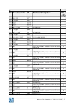
Page 12: ...41 LCD_B5 O5 142 NC LVDS_TX1_DP available on a special version with minimum order quantity X 143 GND PWR 144 NC LVDS_TX1_DN available on a special version with minimum order quantity X 145 LCD_DE O5 1...

Page 13: ...nking with activity 167 CAM_YDATA3 I O parallel camera signal 168 ETH_B_D3_N I Odiff 169 CAM_YDATA5 I O parallel camera signal 170 ETH_B_D3_P I Odiff 171 CAM_YDATA2 I O parallel camera signal 172 GND...

Page 14: ...I Odiff 195 CAM_VSYNC I O parallel camera signal 196 ETH_A_D3_P I Odiff 197 I2C_C_CAMRST I O 198 ETH_A_VLEDOUT PWR 3 3V out for LAN LEDs 199 GND PWR 200 ETH_A_D2_N I Odiff 201 NC 202 ETH_A_D2_P I Odif...

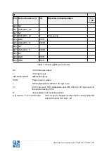
Page 15: ...D PWR 230 GND PWR Table 1 230 pin goldfinger connector O5 3 3V 5mA logic output I 3 3V logic input Idiff Odiff I Odiff differential signal PWR Power input or output SW configurable as GPIO 3 3V logic...

Page 16: ...ion is required nearby the USB connector 217 USB_DEV_VBUS 4 6 5 2V does detect connected USB device Connect with pin 1 on USB device connector 219 USB_DEV_PWR_ONn Low active USB port power on signal U...

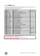
Page 17: ...C SD card A power out 28 SD_A_CLK SD card A clock signal 32 SD_A_DAT0 SD card A data signal 34 SD_A_DAT1 SD card A data signal 81 SD_B_WP SD card B write protect input 83 SD_B_CD SD card B card low ac...

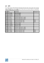
Page 18: ...MISO 52 SPI_B_MOSI SPI port B MOSI 54 SPI_B_SPCK SPI port B Clock 56 SPI_B_CS1 SPI port B chip select 1 output 58 SPI_B_CS2 SPI port B chip select 2 output 60 SPI_B_IRQ1 SPI port B interrupt 1 input...

Page 19: ...a touch controller for resistive or capacitive touch 151 I2C_A_DAT Data signal for touch controller 4k7 PU onboard 155 I2C_A_CLK Clock signal for touch controller 4k7 PU onboard 153 I2C_A_IRQ Interrup...

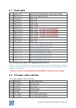
Page 20: ...TXD_E_TTL UART E TX default I2C_B_IRQ 153 RTS_E_TTL UART E RTS default I2C_A_IRQ 116 CTS_E_TTL UART E CTS default I2S_LRCLK 81 RXD_F_TTL UART F RX default SD_B_WP 83 TXD_F_TTL UART F TX default SD_B_...

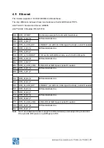
Page 21: ..._A_VLEDOUT 3 3V out for LAN LEDs anode use for both LAN ports 200 ETH_A_D2_N Differential data line 202 ETH_A_D2_P 204 ETH_A_LED_LINK LINK LED at 1GB Speed serial R needed 206 ETH_A_D1_N Differential...

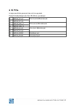
Page 22: ...ted Please following design rules from PCI SIG on your design 41 MPCIE_CTX_P PCIe transmit differential pair 43 MPCIE_CTX_N 47 MPCIE_CRX_P PCIe receive differential pair 49 MPCIE_CRX_N 53 MPCIE_CLK_P...

Page 23: ...LCD_G0 Green0 119 LCD_G1 Green1 121 LCD_G2 Green2 123 LCD_G3 Green3 125 LCD_G4 Green4 127 LCD_G5 Green5 131 LCD_B0 Blue0 133 LCD_B1 Blue1 135 LCD_B2 Blue2 137 LCD_B3 Blue3 139 LCD_B4 Blue4 141 LCD_B5...

Page 24: ...amera interface voltage out 2 8V 191 CAM_HREF I 2 8V CPU pad CSI_HSYNC 195 CAM_VSYNC I 2 8V CPU pad CSI_VSYNC 193 CAM_PWDN O 2 8V High active powerdown signal 197 CAMRST O 2 8V High active reset signa...

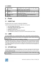
Page 25: ...failures 5 2 eMMC If mounted a eMMC v4 41 or higher with 4GB or more is mounted from several manufacturer This component is optional and not mounted in all configurations Please contact sales to get...

Page 26: ...t more information 6 Power 5V Power In VCC in 5V 5 GND GND connect all GND pins to GND plane VBAT In RTC battery input Leave open if not used V33 Enable 3 3V max 100mA Vout use as enable for main boar...

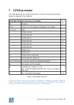
Page 27: ...0 6 LVDS0_DATA2 138 8 LVDS0_CLK 152 9 LVDS0_CLK 150 10 LVDS0_DATA3 24bit only 156 11 LVDS0_DATA3 24bit only 154 12 13 15 16 18 23 n c second channel not available at efusA9X 25 I2C_C_DAT 4k7 PU onboar...

Page 28: ...A9X efus A9Xr2 27 7 1 LVDS EMI filtering The following schematic shows the internal connection of LVDS signals between connector and CPU The common mode chokes are TDK MCZ2010CH240L4T Panasonic EXC 2...

Page 29: ...nt is optional and not mounted in all configurations Please contact sales to get more information Note If WLAN BT module is mounted UART_C is not available on efus B2B connector UART C is used for Blu...

Page 30: ...teria for unintentional radiators in order to be properly authorized for operation as a Part 15 digital device The FCC Part 15 Statement shall be included in the user manual of final commercial produc...

Page 31: ...consumption could be much lower depends CPU workload used graphic interfaces and features and the workload on I O interfaces 10 1 Absolute maximum ratings Description Condition Min Max Unit Input Vol...

Page 32: ...this does not touch the technical characteristics of the product This is necessary to guarantee delivery times and product life A setup of release samples with released second sources is not possible...

Page 33: ...e tray can hold 10 boards An empty tray is used as top cover Figure 3 Tray for shipment 17 Matrix Code Sticker All F S hardware is shipped with a matrix code sticker including the serial number Enter...

Page 34: ...between efusA9X and efusA9Xr2 is the Ethernet Phy efusA9X Qualcomm AR8035 AL1 efusA9Xr2 Realtek RTL8211FD Both Phys are Gbit Phys and are connected by RGMII interface to CPU All frequencies are the sa...

Page 35: ...r use a F S Elektronik Systeme product for any such unintended or unauthorized application the Buyer shall indemnify and hold F S Elektronik Systeme and its officers employees subsidiaries affiliates...

Page 36: ...THE SOLE AND EXCLUSIVE REMEDIES OF ANY PURCHASER WITH RESPECT TO ANY DEFECTIVE PRODUCT Limitation on Liability UNDER NO CIRCUMSTANCES SHALL F S BE LIABLE FOR ANY LOSS DAMAGE OR EXPENSE SUFFERED OR IN...

Reviews: