

12
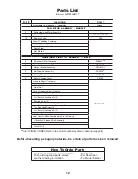
Parts List
Model #FP825**
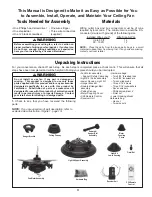
Before discarding packaging materials, be certain all parts have been removed
¾¾
Insert FINISH CODES (Refer to fan model number located on downrod support)
How To Order Parts
Contact your retail store for repair parts.
When ordering repair parts, always
give the following information.
• Part Number
• Part Description
• Fan Model Number
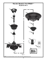
Ref. #
Description
Part #
Retractable Fan Assembly – Traditional
FP825
¾¾
FAN MOTOR ASSEMBLY — MAR20CY
5
Retractable Fan Motor Assembly
—
9
Control Receiver
RECCAN57DEMO
10
Remote Control
C28
Support Cable Bag Containing:
Ceiling Support Cable
Cable Clamp
Flat Washer
Lag Bolt,
3
/
8
˝
x 2
˝
TRADITIONAL LIGHT KIT ASSEMBLY — LK825**
6
5-Socket Light Kit Assembly
AP82530
¾¾
7
Lower Housing, Light Kit
P82515
¾¾
1
Hanger Bracket Assembly
APG610BL
2
Ball/Downrod Assembly
ADR1x6
¾¾
3
Ceiling Canopy
PG165
¾¾
4
Motor Coupling Cover
P81090
8
Hardware Bag(s) Containing:
HDWLK825
¾¾
Wire Nut (7)
Finial Nut
Canopy Hardware Bag Containing:
5
/
32
˝
Threaded Rods (2)
5
/
32
˝
External Lockwasher (2)
Knurled Knobs (2)
Housing Mount Hardware Bag Containing:
3
/
16
˝
Pan Head Screw (3)
3
/
16
˝
External Lockwasher (3)
Phillips Screwdriver, 4
˝
Lower Housing Mounting Hardware Bag Containing:
C-Bracket / Threaded Rod Assembly
Hex Nut
Wire Nut (2)


