background image

Clevis Pin

Setscrew (2)

4

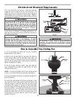
Electrical and Structural Requirements

Ceiling

Ceiling

Joists

2

˝

 x 4

˝

Outlet

Box

Figure 1

How to Assemble Your Ceiling Fan

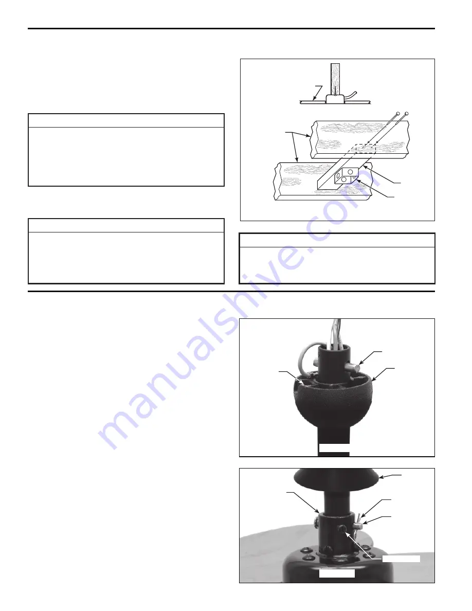
Pin

Setscrew

Hanger

Ball

Figure 1

1. 

Prior to assembly, set aside and save the hardware 

bag(s) packed in the packing.

2. 

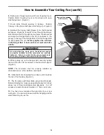
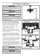
Remove the Hanger Ball by loosening the setscrew 

in the Hanger Ball until the ball falls freely down the 
Downrod. (Figure 1)  Remove the Pin from the Downrod, 
then remove the Hanger Ball.  Retain the Pin and Hanger 
Ball for reinstallation in Step 8.

3. 

The fan comes with blue, black, gray and white 80

˝


wires. Separate and untwist the wires. Route the wires 
through the Downrod.

NOTE: 

 You will be using either the 6

˝

 downrod supplied with 

your fan or an optional downrod purchased seperately.

4.

 Position Fan/Motor Assembly on styrofoam pedestal, for 

ease of assembly. 

5.

 Loosen the two setscrews in the Downrod Support.  Align 

the Clevis Pin holes in the Downrod with the holes in the 
Downrod Support.  Install the Clevis Pin and secure with 
the Hairpin Clip. (Figure 2)  Be sure to push the straight 
leg of the hairpin clip through the hole near the end of the 
clevis pin until the curved portion of the hairpin clip snaps 
around the clevis pin.  The hairpin clip must be properly 
installed to prevent the clevis pin from working loose. Pull 
on the Downrod to make sure the clevis pin is properly 
installed. (Figure 2)

Figure 2

Hairpin Clip

Downrod 

Support

WARNING

To avoid fire or shock, follow all wiring instructions 

carefully.  Any electrical work not described in these 

instructions should be done or approved by a licensed 

electrician.

Motor 

Coupling 

Cover

If your fan is to replace an existing light fixture, turn 
electricity off at the main fuse box at this time and remove 
the existing light fixture.

WARNING

Turning off wall switch is not sufficent.  To avoid 

possible electrical shock, be sure electricity is turned 

off at the main fuse box before wiring.  All wiring must 

be in accordance with National and Local codes and the 

ceiling fan must be properly grounded as a precaution 

against possible electrical shock.

WARNING

To reduce the risk of fire, electrical shock, or personal 

injury, mount fan to outlet box marked acceptable 

for fan support of 22.7 kg (50 lbs) or less. Use screws 

supplied with outlet box.  Most outlet boxes commonly 

used for support of light fixtures are not acceptable for 

fan support and may need to be replaced.  Consult a 

qualified electrician if in doubt.

Your new ceiling fan will require a grounded electrical 
supply line of 120 volts AC, 60 Hz, 15 amp circuit.  The 
outlet box must be securely anchored and capable of 
withstanding a load of at least 22.7 kgs (50 lbs).  

Figure 1


depicts different structural configurations that may be used 
for mounting the outlet box.

Summary of Contents for Air Shadow FP825 Series

Page 1: ...l No FP825 The Air Shadow Traditional Ceiling Fan Net Weight 12 47 kg 27 5 lbs WARNING Support Directly From Building Structure For Canada this fan must be secured directly to the building structure or ceiling joist Don t secure this fan to an outlet box ...

Page 2: ...wner s manual and safety information before installing your new fan Review the accompanying assembly diagrams 2 Before servicing or cleaning unit switch power off at service panel and lock service panel disconnecting means to prevent power from being switched on accidentally When the service disconnecting means cannot be locked securely fasten a warning device such as a tag to the service panel 3 ...

Page 3: ... blade screwdriver One wire stripper Three wire connectors supplied Ceiling Canopy WARNING Do not install or use fan if any part is damaged or missing This product is designed to use only those parts supplied with this product and or any accessories designated specifically for use with this product by Fanimation Substitution of parts or accessories not designated for use with this product by Fanim...

Page 4: ...working loose Pull on the Downrod to make sure the clevis pin is properly installed Figure 2 Figure 2 Hairpin Clip Downrod Support WARNING To avoid fire or shock follow all wiring instructions carefully Any electrical work not described in these instructions should be done or approved by a licensed electrician Motor Coupling Cover If your fan is to replace an existing light fixture turn electricit...

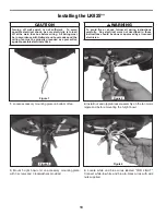
Page 5: ...urely tighten the two 3 16 24 x 3 8 setscrews in the downrod support Figure 2 NOTE The setscrews must be properly installed as described above or fan wobble could result 10 Slide the Motor Coupling Cover down until it touches the top of the Housing Figure 3 11 The fan comes with blue black gray and white leads Before installing fan measure up approximately 6 9 inches above top of Downrod Hanger Ba...

Page 6: ...es omitted for clarity 1 Using the 3 8 x 2 lag bolt and flat washer attach safety cable to ceiling joist or wood structural member The lag bolt will pass through the flat washer safety cable loop the junction box and into the building structure Figure 2 You will first drill a pilot hole into the building structure to prevent splitting or cracking 2 Securely attach the hanger bracket to ceiling jun...

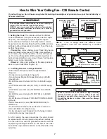
Page 7: ...L to BLACK supply wire WHITE Receiver Unit wire AC IN N to WHITE supply wire WHITE Receiver Unit wire TO MOTOR N to WHITE fan wire BLACK Receiver Unit wire TO MOTOR L to BLACK fan wire BLUE Receiver Unit wire FOR LIGHT DOWN to BLUE light wire GRAY Receiver Unit wire REVERSE MODULE to GRAY wire Position all connected wires and receiver antenna to allow installation of ceiling canopy Using canopy sc...

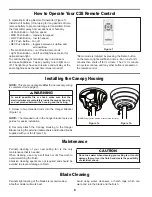
Page 8: ...using water cleansers or harsh rags which can warp and ruin the blade and the finish CAUTION Do not use water when cleaning your ceiling fan It could damage the motor or the finish and create the possibility of electrical shock How to Operate Your C28 Remote Control 1 Operating Using Remote Transmitter Figure 1 Install 9 volt battery If not using for long periods of time remove battery to prevent ...

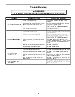
Page 9: ... tight 2 Check to make sure wire connectors in switch housing are not rattling against each other or against the interior wall of the switch housing CAUTION Make sure main power is turned off 3 Some fan motors are sensitive to signals from solid state variable speed controls Solid state controls are not recommended choose an alternative control method 4 Tighten screws securely 5 Tighten set screw ...

Page 10: ...d before mounting the 5 light bowl 3 Mount 5 light bowl unit on accessory mounting plate with 3 screws and 3 lockwashers provided 4 Locate white and blue wires labeled FOR LIGHT Connect white to white and blue to black wires with wire nuts supplied CAUTION Turning off wall switch is not sufficient To avoid possible electrical shock be sure electricity is turned off at the main fuse box before wiri...

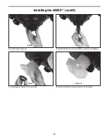
Page 11: ...the LK825 cont d Figure 5 Figure 6 Figure 7 Figure 8 5 Install lower housing 6 Install finial nut on end of nipple do not over tighten 7 Install glass shades not included 8 Install 60 watt med base bulbs not included ...

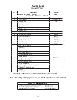
Page 12: ...O 10 Remote Control C28 Support Cable Bag Containing Ceiling Support Cable Cable Clamp Flat Washer Lag Bolt 3 8 x 2 TRADITIONAL LIGHT KIT ASSEMBLY LK825 6 5 Socket Light Kit Assembly AP82530 7 Lower Housing Light Kit P82515 1 Hanger Bracket Assembly APG610BL 2 Ball Downrod Assembly ADR1x6 3 Ceiling Canopy PG165 4 Motor Coupling Cover P81090 8 Hardware Bag s Containing HDWLK825 Wire Nut 7 Finial Nu...

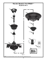
Page 13: ...13 NOTE The illustration shown is not to scale or its actual configuration may vary The Air Shadow Fan FP825 Exploded View 4 1 Figure 1 3 6 5 2 7 8 8 ref 9 10 8 ref ...

Page 14: ...10983 Bennett Parkway Zionsville IN 46077 888 567 2055 FAX 866 482 5215 Outside U S call 317 733 4113 Visit Our Website www fanimation com Copyright 2007 Fanimation 2007 01 ...

Reviews: