
6
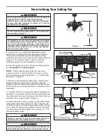
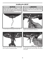
How to Hang Your Ceiling Fan
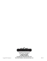
Figure 1
Floor
No
less than
7 ft
▲
WARNING
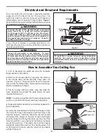
The fan must be hung with at least 7´ of clearance from
floor to blades (Figure 1)
▲
WARNING
The outlet box must be securely anchored and capable
of withstanding a load of at least 50 lbs. Hanger bracket
must seat firmly against outlet box. If the outlet box is
recessed, remove wallboard until bracket contacts box.
If bracket and/or outlet box are not securely attached,
the fan could wobble or fall.
▲
WARNING
Failure to seat tab in groove could cause damage to
electrical wires and possible shock or fire hazard.
▲
WARNING
To avoid possible shock, do not pinch wires between the
downrod/hanger ball assembly and the hanger bracket.
▲
WARNING
To avoid possible electrical shock, be sure electricity is
turned off at the main fuse box before hanging.
NOTE: If you are not sure if the outlet box is grounded,
contact a licensed electrician for advice, as it must be
grounded for safe operation.
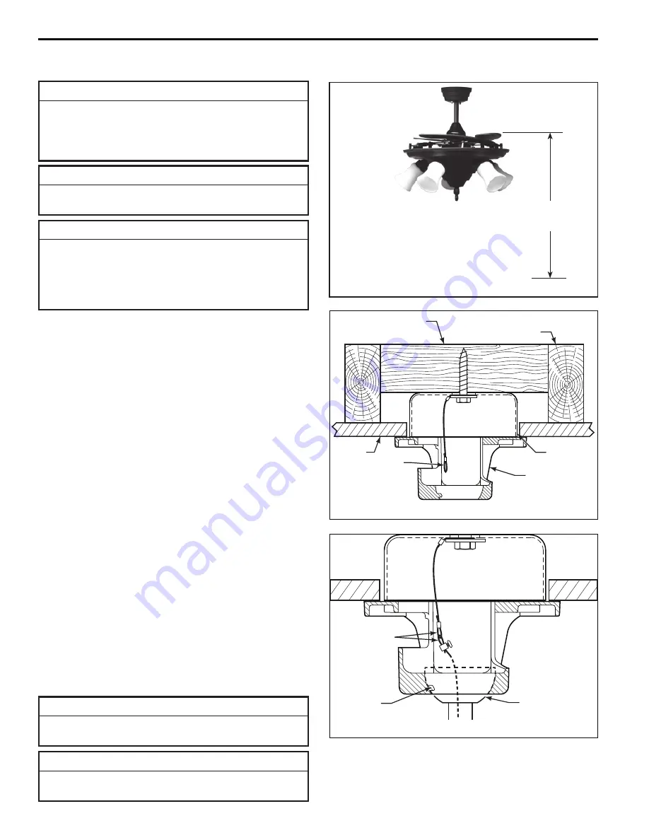
Ceiling Joist
Wood Member
(2
˝
x 4
˝
Approx.)
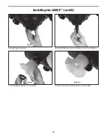
Figure 2
Junction
Box
Ceiling
Support
Cable
Hanger Bracket
Ceiling
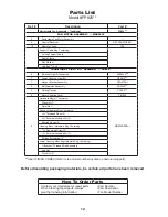
Figure 3
Downrod/Hanger
Ball Assembly
Attach
Safety Cable to
Ceiling Support
Cable
Tab
NOTE:
Supply wires and
fan wires omitted for clarity
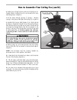
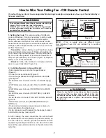
1.
Using the
3
⁄
8
˝
x 2
˝
lag bolt and flat washer, attach
safety cable to ceiling joist or wood structural member.
The lag bolt will pass through the flat washer, safety
cable loop, the junction box and into the building structure
(Figure 2). You will first drill a ¼
˝
pilot hole into the
building structure to prevent splitting or cracking.
2.
Securely attach the hanger bracket to ceiling junction
box
acceptable for ceiling support
.
NOTE:
Ceiling support cable cannot be secured to
junction box only, it must be directly secured to ceiling
joist or structural member
using the
⅜
˝
x 2
˝
lag bolt and
fl
at washer.
(Figure 2).
3.
Make sure the electrical supply wires, including the
hanger bracket grounding wire and safety cable are
pulled through the downrod, between the hanger bracket
and the junction box so that electrical connections can be
made later.
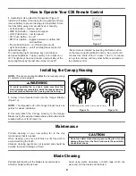
4.
Carefully lift the fan and seat the downrod/hanger ball
assembly on the hanger bracket that was just attached to
the ceiling joist. Be sure the groove in the ball is lined up
with tab on the hanger bracket. (Figure 3)
5.
Attach the safety cable to ceiling support cable. Slide
cable clamp onto safety cable (from fan). Place the end
of cable through the loop of ceiling support cable. Pull as
much cable through loop as possible. Feed end of cable
into clamp hole and firmly tighten screw (Figure 3). Cut
off excess safety cable.


