background image

Fan Chain Coupler

16

HOW TO ORDER REPAIR PARTS

When ordering repair parts, always give the following information:

Part Number

Part Description

Fan Model Number

Contact your retail store for repair parts.

Before discarding packaging material, be certain all parts have been removed.

** Insert FINISH CODES (Refer to fan model number located on downrod support)

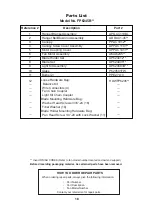
Parts List

Model No. FP6244**

Reference #

Part #        


ADRAC1-45**
PPAC1012**

APPAC1411**


Motor Coupling Cover 

AP624412**

AMA6244**

Blade Holder Set

Fan Motor Assembly

AP624405**

Blade Set

AP624404**

APGAC110BL

APPAC1101**

Switch Cup Assembly

HDWFP6244**

1
2
3

4

5
6
7
8
9

10


Hanger Bracket Assembly 

Hanger Ball/Downrod Assembly 
Canopy
Canopy Screw Cover Assembly

Wire Connectors (4)

Loose Hardware Bag:

Blade Mounting Hardware Bag:

Washer Head Screws 3/16˝-24 (16)

Fiber Washer (16) 

Blade Holder Mounting Hardware Bag:

Pan Head Screw 1/4˝-20 with Lock Washer (11) 

Balance Kit

Description   

Summary of Contents for AIRE DELUXE

Page 1: ...ms missing parts Before returning to your retailer call our customer service department at 1 888 567 2055 8 a m 5 p m EST Monday Friday ATTACH YOUR RECEIPT HERE READ AND SAVE THESE INSTRUCTIONS Purcha...

Page 2: ...chaser of a Fanimation Fan Important Safety Instructions WARNING To avoid fire shock and serious personal injury follow these instructions Table of Contents Unpacking Instructions 3 Energy Ef cient Us...

Page 3: ...ssembly FP6245B Glass FP6245B ardware ags 1 4 20 pan head screws blade holder to fan motor hub 3 16 24 washer head screws blade to blade holder Fiber Washer our ire Connectors alance it with lock wash...

Page 4: ...raft which forces warm air near the ceiling down into the occupied space Remember to adjust your thermostat when using your ceiling fan additional energy and dollar savings could be realized with this...

Page 5: ...reduce the risk of fire electrical shock or personal injury mount fan to outlet box marked acceptable for fan support of 15 88 kg 35 lbs or less Use screws supplied with outlet box Most outlet boxes...

Page 6: ...nrod support on top of the motor Install the clevis pin by aligning the holes in the downrod support with holes in the downrod Secure clevis pin with hairpin clip Tighten the two set screws with nuts...

Page 7: ...2 inch from the end of each lead wire Figure 7 6 Reinstall the hanger ball on the downrod as follows Route the black white and blue wires through the hanger ball Position the pin through the two hole...

Page 8: ...the ball is lined up with tab on the hanger bracket Figure 4 WARNING Failure to seat tab in groove could cause damage to electrical wires and possible shock or re hazard WARNING To avoid possible shoc...

Page 9: ...ire is visible at the wire connectors except for the ground wire Do not operate fan until the blades are in place Noise and fan damage could result 1 Connect the green grounding lead from the hanger b...

Page 10: ...and not pinched between the housing and the ceiling NOTE This step is applicable after the neccessary wiring is completed Canopy Screw Cover Figure 2 Ceiling Canopy Figure 1 10 HARDWARE USED x 15 x 15...

Page 11: ...ED x 10 SCREWS Figure 3 Screws Figure 1A Figure 1B FP6244 FP6245B Figure 3A Figure 3B FP6244 FP6245B Figure 2 2 Remove one of the three screws in the support bracket Slightly loosen the remaining two...

Page 12: ...light kit CAUTION 6 Disassemble the finial trim cover and nut in light kit assembly Securely attach the glass to light kit assembly using supplied nut trim cover and finial Do not over tighten Figure...

Page 13: ...Chain Operating Sequence Figure 2A Figure 2B FP6244 FP6245B Figure 3 FP6244 FP6245B Figure 5 FP6244 FP6245B Reverse Switch Information Season Rotation Direction Switch Position Summer Counter Clockwis...

Page 14: ...s to motor flywheel are loose 4 Wire connectors inside housing rattling 5 Screws holding blades to blade holders are loose 3 FAN WOBBLES EXCESSIVELY 1 Tighten both setscrews securely in downrod suppor...

Page 15: ...are not required and should be avoided to prevent damage to finish Do not use water when cleaning your ceiling fan It could damage the motor or the finish and create the possibility of electrical sho...

Page 16: ...rt Parts List Model No FP6244 Reference Part ADRAC1 45 PPAC1012 APPAC1411 Motor Coupling Cover AP624412 AMA6244 Blade Holder Set Fan Motor Assembly AP624405 Blade Set AP624404 APGAC110BL APPAC1101 Swi...

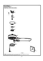
Page 17: ...4 Exploded View Illustration NOTE The illustration shown is not to scale or its actual con guration may vary Product parts are subject to change without notice Figure 1 1 2 3 4 5 6 9 Aire Deluxe 10 10...

Page 18: ...Wire Connectors 4 Loose Hardware Bag Blade Mounting Hardware Bag Washer Head Screws 3 16 24 16 Fiber Washer 16 Blade Holder Mounting Hardware Bag Pan Head Screw 1 4 20 with Lock Washer 11 Balance Kit...

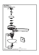
Page 19: ...ed View Illustration NOTE The illustration shown is not to scale or its actual con guration may vary Product parts are subject to change without notice Figure 1 1 2 3 4 5 6 e x u l e D e r i A 12 12 1...

Page 20: ...Copyright 2017 Fanimation 2017 02 V 01 10983 Bennett Parkway Zionsville IN 46077 Phone 888 567 2055 Outside U S 317 733 4113 FANIMATION COM FAX 866 482 5215...

Page 21: ...8 lbs FP6245B Peso neto 7 51 kgs 16 56 lbs Adjunte su recibo AQU LEA Y GUARDE ESTAS INSTRUCCIONES Fecha de compra Preguntas problemas piezas faltantes Antes de volver a la tienda llame a nuestro Depar...

Page 22: ...strucciones de seguridad importantes ADVERTENCIA Siga estas instrucciones para prevenir incendios descargas el ctricas y lesiones personales graves Lea el manual del propietario y la informaci n de se...

Page 23: ...de completar todos los pasos y podr saber desde d nde retomar si fuera interrumpido Bolsas de accesorios Conectores de cables Acoplador de la cadena del tirador del ventilador FP6244 FP6245B Acoplado...

Page 24: ...tamosalgunassugerencias para asegurar un rendimiento eficiente del producto Selecci n del lugar de montaje adecuado Los ventiladores de techo se deben instalar en el centro de la habitaci n a 2 13 m 7...

Page 25: ...pagar el interruptor de pared no es suficiente Para evitar posibles descargas el ctricas aseg rese de que la electricidad est desconectada en la caja de fusibles principal antes de realizar la instala...

Page 26: ...varilla y alinee los orificios de la clavija de horquilla en ambas piezas Instale la clavija de horquilla y aseg rela con la pinza de horquilla Fije los dos tornillos de presi n y las tuercas de segu...

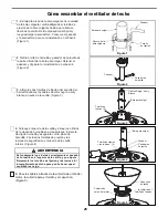
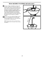
Page 27: ...a colocar la semiesfera en el barral como se indica a continuaci n Pase los tres cables de cables de blanco negro y azul cable de soporte para techo a trav s de la semiesfera Pase el pasador a trav s...

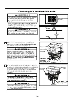
Page 28: ...a una distancia m nima de 2 13 m desde las aspas hasta el piso Figura 2 Figura 1 ADVERTENCIA NOTA Si no est seguro de si la caja de salida tiene conexi n a tierra pida consejo a un electricista certif...

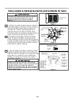
Page 29: ...n el conductor con conexi n a tierra y el conductor con conexi n a tierra del equipo debe ir en un lado de la caja de distribuci n el ctrica y el conductor sin conexi n a tierra debe ir del otro lado...

Page 30: ...descargas el ctricas aseg rese de que los cables el ctricos vuelta hacia arriba y completamente empujarse con cuidado en el cuadro de juntura y de que no est n aprisioel techo Cubierta de uni n del mo...

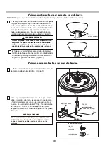
Page 31: ...ducir el riesgo de lesiones personales no doble los soportes de aspas al instalarlos balancear las aspas o limpiar el ventilador No coloque objetos extra os entre las aspas del ventilador en funcionam...

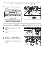
Page 32: ...adaptador de 9 pines desde el motor a la sujeci n del arn s del cable ubicado dentro de la unidad del kit de iluminaci n Figura 3B C mo ensamblar su unidad de interruptor unidad del kit de iluminaci n...

Page 33: ...tirando levemente de la cadena de encendido apagado para el control de la velocidad Figura 3 1 tirada 2 tirada 3 tirada 4 tirada Alta Apagado Baja Media Secuencia de funcionamiento de la cadena del ti...

Page 34: ...an los soportes de las aspas al buje del motor est n flojos 4 Los soportes de aspas no est n colocados correctamente 5 El soporte de suspensi n o la caja de distribuci n el ctrica del techo no est n b...

Page 35: ...cepillo suave o un pa o sin pelusas para evitar rayar el acabado No se requieren agentes abrasivos de limpieza los mismos deben evitarse para prevenir da os en el acabado PRECAUCI N No utilice solven...

Page 36: ...ad del soporte de suspensi n Unidad del barral de la semiesfera Capuch n de techo Cubierta para el tornillo del capuch n Descripci n N de Ref Pieza N Modelos N FP6244 Lista de piezas 36 ADRAC1 45 PPAC...

Page 37: ...37 Figura 1 1 2 3 4 5 6 9 Aire Deluxe 10 10 10 10 7 8 10 Modelo N FP6244 Ilustraci n del despiece NOTA...

Page 38: ...P6245 1 2 3 4 5 6 7 8 9 P624501FW Vidrio PPE27L10 Bombillas 2 10 11 12 Modelos N Descripci n N de Ref Pieza N FP6245B Lista de piezas 38 Cubierta de uni n del motor Unidad del motor del ventilador Uni...

Page 39: ...11 10 9 12 12 Aire Deluxe Modelo N FP6245B Ilustraci n del despiece NOTA 39 Figura 1 1 2 3 4 5 6 12 12 12 12 7 8...

Page 40: ...17 Fanimation 2017 02 V 01 Visite nuestro sitio Web en www fanimation com 10983 Bennett Parkway Zionsville IN 46077 Llame sin cargo al 888 567 2055 FAX 866 482 5215 Desde fuera de los EE UU llame al 3...

Reviews: