background image

3

Before assembling your ceiling fan, refer to section on 

proper method of wiring your fan (page 5).  If you feel 

you do not have enough wiring knowledge or experience, 

have your fan installed by a licensed electrician.

WARNING

This Manual is Designed to Make it as Easy as Possible for You

to Assemble, Install, Operate, and Maintain Your Ceiling Fan

Do not install or use fan if any part is damaged or missing.  

This product is designed to use only those parts supplied 

with this product and/or any accessories designated 

speci

fi

 cally for use with this product by Fanimation. 


Substitution of parts or accessories not designated 

for use with this product by Fanimation could result in 

personal injury or property damage.  Contact your retail 

store for missing or damaged parts.

WARNING

Unpacking Instructions

For your convenience, check-off each step.  As each step is completed, place a check mark.  This will ensure that all 
steps have been completed and will be helpful in 

fi

 nding your place should you be interrupted. 

Wiring outlet box and box connectors must be of type 

required by local code.  The minimum wire would be a 3-

conductor (2-wire with ground) of the following size:

NOTE:

  Place the parts from the loose parts bags in a 

small container to keep them from being lost.  If any parts 

are missing, contact your local retailer.

Tools Needed for Assembly

Materials

Wire Size A.W.G.

Installed Wire Length

14

12

Up to 50 ft.

50 - 100 ft.

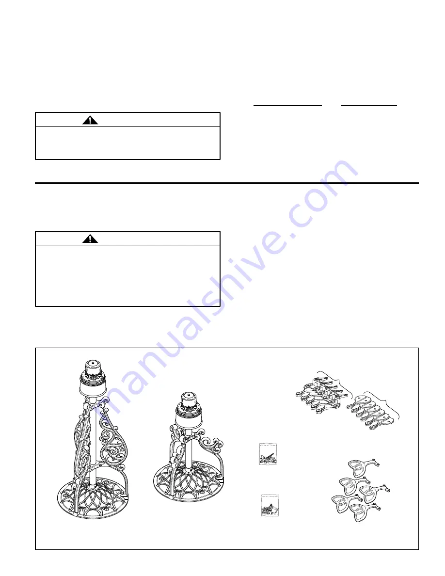
Check to see that you have received the following parts:

• Fan Motor/Base Assembly

• Blade Holder pack (5)

• Blade Mounting Hardware Bag

• Hardware bag:

    – Three 3” lag bolts

    – Three 

5

16

” washers

    – Three wire connectors

    – 10-32 x ½” flywheel screws (10 pcs)

• One Phillips head screwdriver
• One stepladder
• One 1/4” blade screwdriver
• One wire stripper


Three wire connectors

  (supplied)


7

16

½”


&


9

16


wrench

  or socket wrench

Hardware Bag

Blade Holder Pack

(Wooden Blades only)

Side B

Side A

Blade Mounting

Hardware Bag

Blade Holder Pack

(Palm, Wicker,

& Bamboo blades)

Americana Long

Fan Motor/

Base Assembly

NOTE:

  If you are uncertain of part description, refer to

exploded view illustration. (Figure 7, page 9)

NOTE:

  Blades are sold seperately.

Americana Short

Fan Motor/

Base Assembly

Summary of Contents for Americana FP410 Series

Page 1: ...Net Weight Long 41 lbs Net Weight Short 32 lbs OWNER S MANUAL READ AND SAVE THESE INSTRUCTIONS Model No FP410 Short Model No FP420 Long The Americana Ceiling Fan ...

Page 2: ...erwise be accorded by law This warranty gives you special legal rights and you may also have other rights that vary from state to state 10 A certain amount of wobble is normal and should not be considered a problem or a defect 1 Read your owner s manual and safety information before installing your new fan Review the accompanying assembly diagrams 2 Before servicing or cleaning unit switch power o...

Page 3: ...place should you be interrupted Wiring outlet box and box connectors must be of type required by local code The minimum wire would be a 3 conductor 2 wire with ground of the following size NOTE Place the parts from the loose parts bags in a small container to keep them from being lost If any parts are missing contact your local retailer Tools Needed for Assembly Materials Wire Size A W G Installed...

Page 4: ...st drill a 1 4 pilot hole into the plywood base or supporting member to prevent splitting or cracking Mount the assembled fan on the ceiling with 3 lag bolts and flat washers 2 While supporting the Fan Motor Base Assembly screw the lag bolts approximately half way to allow enough space between ceiling panel and fan base in order to properly wire your fan 3 After the connections have been made tigh...

Page 5: ...nnections have been made turn leads upward and carefully push leads into the outlet box with the white and green leads on one side of the outlet box and the black and blue leads on the other side of the outlet box Figure 3 Junction Box Figure 2 Figure 4 Reversing Switch Speed Control Pull Chain 1 Restore electrical power to the outlet box by turning the electricity on at the main fuse box 2 Check ...

Page 6: ...de holder on a flat surface with the inside of the blade holder facing up This is the side with the threaded posts and pitched foot Figure 5 2 Position the palm leaf or the woven bamboo blade over the blade holder with the threaded posts showing Make sure the bottom edge of the blade is fully seated against the blade holder 3 Place side B of the blade holder on top of the blade positioning the hol...

Page 7: ...blades to blade holders are loose 7 Rubber flywheel set screw loose 1 Attach blades to fan before operating 2 Check to make sure all screws in motor housing are snug not over tight 3 Check to make sure the screws which attach the fan blade holders to the motor flywheel are tight 4 Check to make sure wire connectors in switch housing are not rattling against each other or against the interior wall ...

Page 8: ...08 7a Short Leg Americana Short Model 3 P510 8 Hex Head Bolt 20 x 1 Black 6 FAHEX312 9 Flat Washer Black 9 FAWASH716 10 Hex Head Bolt 20 x 1 Black 3 FAHEX302 11 Flat Washer Black 9 FAWASH716 12 Fan Base 1 P502 13 Wall Flange 1 1 P404 14 Socket Cap Screw 10 32 x 3 FASOCK902 15 Nut Hex 10 32 3 FANUT808 16 Mounting Screw 10 32 x 1 3 17 Nut Hex 10 32 3 FANUT808 18 Nut Hex 20 Black 3 FANUT810 19 Blade ...

Page 9: ...shown is not to scale or its actual configuration may vary wires partially removed for clarity Exploded View The Americana Side B Side A 21 22 3 18 12 25 17 11 8 8 9 7 9 1 6 24 2 20 4 5 6 10 19 23 Figure 7 9 7a 5 15 16 13 14 ...

Page 10: ...10983 Bennett Parkway Zionsville IN 46077 Toll Free 888 567 2055 FAX 866 482 5215 Outside U S call 317 733 4113 Visit Our Website www fanimation com Copyright 2008 Fanimation 2008 06 ...

Reviews: