


7
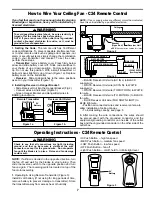
How to Wire Your Ceiling Fan - C24 Remote Control
Operating Instructions - C24 Remote Control
1.
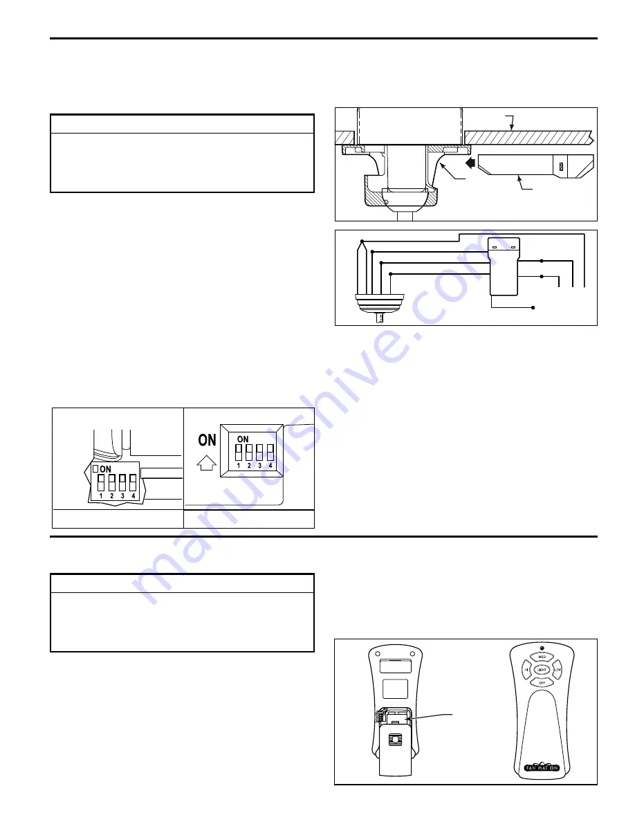
Operating & Using Remote Transmitter (Figure 3):
Install 9 volt battery (If not using for long periods of time,
remove battery to prevent damage to transmitter). Store
the transmitter away from excess heat or humidity.
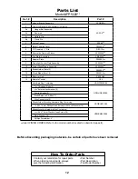
1. Setting the Code:
The remote unit has 16 different
code combinations. To prevent possible interference from
or to other remote units such as garage door openers, car
alarm or security systems, simply change the combination
code in your transmitter and receiver. To set the code,
perform these steps.
• Transmitter:
remove battery cover. Press firmly below
arrow and slide battery cover off. Slide code switches to
your choice of up or down position. Factory setting is all
up. Do not use this position. With a small screwdriver or
ball point pen slide firmly up or down (Figure 1a). Replace
battery cover on the transmitter.
• Receiver:
Slide code switches to the same positions
as set on your transmitter (Figure 1b).
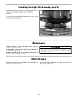
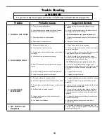
2. Installing Receiver in Hanger Bracket:
• Slide Receiver Unit into the Hanger Bracket (Fig 2).
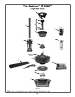
• Connect wires as indicated: (Figure 3)
– Green Hanger Bracket and Hanger Ball wires to
BARE (ground) wire.
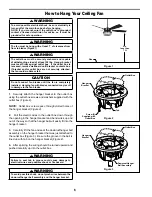
If you feel that you do not have enough electrical wiring
knowledge or experience, have your fan installed by a
licensed electrician.
– BLACK Receiver Unit wire (AC IN L) to BLACK
supply wire.
– WHITE Receiver Unit wire (AC IN N). to WHITE
supply wire.
– WHITE Receiver Unit wire (TO MOTOR N) to WHITE
fan wire.
– BLACK Receiver Unit wire (TO MOTOR L) to BLACK
fan wire.
– BLUE Receiver Unit wire (FOR DOWN LIGHT) to
BLUE light wire.
• Position all connected wires and receiver antenna to
allow installation of ceiling canopy.
• To install ceiling canopy, see page 8.
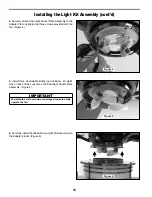
3.
After making the wire connections, the wires should
be spread apart with the grounded conductor and the
equipment-grounding conductor on one side of the outlet
box and the ungrounded conductor on the other side of the
outlet box.
NOTE:
If fan or supply wires are different colors than indicated,
have this unit installed by a quali
fi
ed electrician.
NOTE:
If airflow is desired in the opposite direction, turn
the fan off and wait for the blades to stop turning. Then
slide the reverse switch to the opposite position and turn
fan on again. The reversing switch is located on top of the
fan motor assembly.
• HI Push Button – high fan speed
• MED Push Button – medium fan speed
• LOW Push Button – low fan speed
• OFF Push Button – fan off
• Light Push Button – on/off, hold for infinite light level
Figure 2
Figure 3
Figure 1b
Figure 1a
Figure 3
Receiver Unit
Ceiling
Bracket
(Open End)
BLK-ANT
BL-AC IN L
WH-AC IN N
BLUE-FOR DOWN LIGHT
BLK-TO MOTOR L
WH-TO MOTOR N
GRN or BARE GROUND
GRN from hanger ball
GRN from bracket
9V
Battery
Remote Transmitter
Unit Detail
Reciever Unit Detail
9V
Battery
120 VAC SUPPLY
(User Supplied)
NOTE:
Receiver wires omitted for clarity.
▲
WARNING
To avoid possible electrical shock, be sure electricity is
turned off at the main fuse box before wiring.
NOTE: If you are not sure if the outlet box is grounded,
contact a licensed electrician for advice, as it must be
grounded for safe operation.
▲
WARNING
Check to see that all connections are tight, including
ground, and that no bare wire is visible at the wire
connectors, except for the ground wire. Do not operate
fan until the blades is in place. Noise and fan damage
could result.
Summary of Contents for Andover FP5220 Series
Page 15: ......


