background image

6

Electrical and Structural Requirements (Continued)

Turning off wall switch is not sufficient. To avoid
possible electrical shock, be sure electricity  is
turned  off  at  the  main  fuse  box  before  wiring. All
wiring must be in accordance with National and
Local codes and the ceiling fan must be properly
grounded as a precaution against possible electrical
shock.

WARNING

To reduce the risk of fire, electrical shock,   or
personal injury, mount fan to outlet box marked
acceptable for fan support of 15.88 kg (35 lbs) or less.
Use screws supplied with outlet box. Most outlet
boxes commonly used for support of light fixtures
are  not  acceptable  for  fan  support  and  may  need  to
be replaced. Consult  a  qualified electrician  if
in doubt.

WARNING

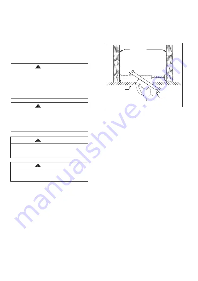
Brace use (Figure 3)

Paired with a deep box, this hanger is meant to span 
between two joists and takes the place of wooden 
blocking.

To  avoid  fire  or  shock,  follow  all  wiring  instructions
carefully.  Any  electrical  work  not  described  in  these
instructions should be done or approved by a
licensed electrician.

WARNING

Figure 3

CEILING JOIST

CEILING

OUTLET BOX

Do not operate this fan with a variable (Rheostat) wall 
controller or dimmer switch. Doing so could result in 
damage to the ceiling fan's remote control unit.

WARNING

Summary of Contents for ARCHIVE LP3071 Series

Page 1: ...m 5 p m EST Monday Friday ATTACH YOUR RECEIPT HERE AND REGISTER YOUR FAN AT FANIMATION COM READ AND SAVE THESE INSTRUCTIONS Date Code Purchase Date Net Weight 10 36 lbs 4 70 kg For best and quickest...

Page 2: ...imits for Class B digital device pursuant to part 15 of the FCC Rules These limits are designed to provide reasonable protection against harmful interference in a residential installation This equipme...

Page 3: ...not the store that sold the fan or Fanimation 7 Fanimation reserves the right to modify or discontinue any product at any time and may substitute any part under this warranty LIMITED LIFETIME WARRANT...

Page 4: ...ls Needed for Assembly Not Included Hand held Remote 1 Wall Holder 1 Screws 2 Battery 1 Receiver 1 Wire Connectors 6 12V 23A NOTE If you are uncertain of part description refer to exploded view illust...

Page 5: ...to blocking between joists and is roomy enough to handle more than one cable Choosing the Appropriate Mounting Location Winter Season Reverse the motor and operate the ceiling fan at low speed in the...

Page 6: ...ws supplied with outlet box Most outlet boxes commonly used for support of light fixtures are not acceptable for fan support and may need to be replaced Consult a qualified electrician if in doubt WAR...

Page 7: ...lling 2 Remove the hairpin clip and clevis pin from the bottom of the downrod Retain the pin and clip for reinstallation in Step 4 Figure 2 Downrod Set Screws and Locking Nuts 2 Clevis Pin Hairpin Cli...

Page 8: ...later Figure 6 7 Assemble the upper decorative trim to the motor assembly using the previously removed cap nuts and securely tighten all three cap nuts Figure 7 8 Route wires through canopy screw cove...

Page 9: ...holes in the downrod and align the hanger ball so the pin is captured in the groove in the top of the hanger ball Pull the hanger ball up tight against the pin Securely tighten the set screw in the h...

Page 10: ...and washers supplied with the outlet box Figure 3 WARNING Figure 3 Outlet Box Hanger Bracket Screw 2 Supplied with Outlet Box Tab Flat Washer Figure 4 Outlet Box Hanger Bracket Downrod Hanger Ball As...

Page 11: ...operation CAUTION INCORRECT WIRE CONNECTION WILL DAMAGE THIS RECEIVER 1 To set the code on receiver unit slide dip switches to the same positions as set on the remote Figure 1 NOTE Factory setting is...

Page 12: ...unit Securely enclose the red supply wire with wire connector Figure 4 4 After connections have been made the wires should be spread apart with the grounded conductor and the equipment grounding condu...

Page 13: ...en shoulder screw Fully assemble and tighten second shoulder screw that was previously removed Figure 1 2 Securely attach and tighten the canopy screw cover over the shoulder screws in the hanger brac...

Page 14: ...this fan with a variable Rheostat wall controller or dimmer switch Doing so could result in damage to the ceiling fan s remote control unit 14 3 To make fan operational install 23A 12V battery includ...

Page 15: ...should be avoided to prevent damage to finish Screws 2 Wall Holder Figure 5 Reverse Switch Figure 6 6 If airflow is desired in the opposite direction turn the fan off and wait for the blades to stop...

Page 16: ...mbly Hanger Ball Downrod Assembly Ceiling Canopy Canopy Screw Cover Assembly P307101 Upper Decorative Trim Before discarding packaging material be certain all parts have been removed Insert FINISH COD...

Page 17: ...NOTE The illustration shown is not to scale or its actual configuration may vary Product parts are subject to change without notice ARCHIVE TM Model LP3071 Exploded View Illustration 8 10 9 1 2 3 5 6...

Page 18: ...groove assembly is loose 4 Hanger bracket and or ceiling outlet box is not securely fastened 5 NOT ENOUGH AIR MOVEMENT 4 Dead battery in remote control 4 Replace with new battery 1 Check to make sure...

Page 19: ...Copyright 2022 Fanimation 2022 06 V 01 10983 Bennett Parkway Zionsville IN 46077 Phone 888 567 2055 Outside U S 317 733 4113 www fanimation com FAX 866 482 5215...

Page 20: ...DJUNTE SU RECIBO AQU Y REGISTRE SU VENTILADOR EN FANIMATION COM LEA Y GUARDE ESTAS INSTRUCCIONES C digo de fecha Fecha de compra Peso neto 4 70 kg 10 36 lbs Para ofrecer un servicio r pido y de calida...

Page 21: ...oportes de las aspas borde o soporte de aspas al instalar los soportes balancear las aspas o limpiar el ventilador No coloque objetos extra os entre las aspas del ventilador en funcionamiento 1 Este e...

Page 22: ...as diversas condiciones clim ticas esta garant a no cubre cambios en la terminaci n incluidos oxidaci n corrosi n falta de brillo o peladuras 5 Esta garant a es nula y no se aplica a da os por instala...

Page 23: ...ara el tornillo del capuch n 1 Unidad del barral de la semiesfera 1 Varilla 1 Bola colgante 1 Tornillo de fijaci n 1 Clip de horquilla 1 Pasador de horquilla 1 Pasador 1 Mano a distancia 1 Placa de la...

Page 24: ...energ a de los ventiladores de techo dependen de su correcta instalaci n y uso Acontinuaci n le presentamos algunas sugerencias para asegurar un rendimiento eficiente del producto Uso del ventilador...

Page 25: ...lador de techo 25 Para reducir el riesgo de incendios descargas el ctricas o lesiones personales fije el ventilador a la caja de distribuci n el ctrica marcada como aceptable para soporte de ventilado...

Page 26: ...damental que instale correctamente el pasador de horquilla en el soporte de la varilla y que ajuste firmemente los tornillos de fijaci n y las tuercas El incumplimiento de dicho paso podr a hacer que...

Page 27: ...desde el motor del ensamble y gu rdelos para despu s Figura 6 7 Instale la ribete decorativo superior en la motor usando las el tuercas retirados previamente y fije bien los tres tuercas Figure 7 Moto...

Page 28: ...i n Pase los cables de negro y blanco a trav s de la semiesfera Pase el pasador a trav s de los dos orificios en el barral y alinee la semiesfera de modo que el pasador quede atrapado en la ranura de...

Page 29: ...r y la abrazadera para colgar ADVERTENCIA ADVERTENCIA Para evitar una posible descarga el ctrica aseg rese de cortar la alimentaci n el ctrica de la caja de fusibles principal antes de colgar el venti...

Page 30: ...est seguro de si la caja de salida tiene conexi n a tierra pida consejo a un electricista certificado ya que debe tener conexi n a tierra para un funcionamiento seguro PRECAUCI N UNA CONEXI N INCORRE...

Page 31: ...a unidad receptora marcado AC IN N al conductor blanco de alimentaci n con el conector de cables Conecte el conductor blanco de la unidad receptora marcado TO MOTOR N al conductor blanco del ventilado...

Page 32: ...r de techo C mo utilizar su ventilador de techo Figura 2 Figura 1 Solo para referencia visual no ha sido dise ado para cubrir todos los tipos de controles PRINCIPAL CAJA DE FUSIBLES 32 C mo instalar l...

Page 33: ...siga el proceso de fijaci n remota de c digo Si no se utiliza el ventilador durante un largo periodo de tiempo extraiga la bater a para evitar cualquier da o al transmisor Almacene el mando a distanci...

Page 34: ...pelusas para evitar rayar el acabado No se requieren agentes abrasivos de limpieza los mismos deben evitarse para prevenir da os en el acabado 6 Si se desea que el flujo del aire vaya en la direcci n...

Page 35: ...el tornillo de fijaci n en la unidad del barral de la semiesfera 4 Ajuste los tornillos del soporte de suspensi n de la caja de distribuci n el ctrica y aseg rela 5 NO HAY SUFICIENTE MOVIMIENTO DE AI...

Page 36: ...ra el tornillo del capuch n P307101 Ribete Decorativo Superior Antes de desechar los materiales de embalaje aseg rese de haber extra do todas las piezas Inserte los C DIGOS DE ACABADO consulte el n me...

Page 37: ...37 NOTA 8 10 9 1 2 3 5 6 7 ARCHIVE TM Modelo N LP3071 Ilustraci n del despiece 4...

Page 38: ...Copyright 2022 Fanimation 2022 06 V 01 10983 Bennett Parkway Zionsville IN 46077 Llame Sin Cargo al 888 567 2055 Desde fuera de los EE UU llame al 317 733 4113 www fanimation com FAX 866 482 5215...

Reviews: