Figure 1
For illustrative purposes only
-not
intended to cover all types of controls
1.
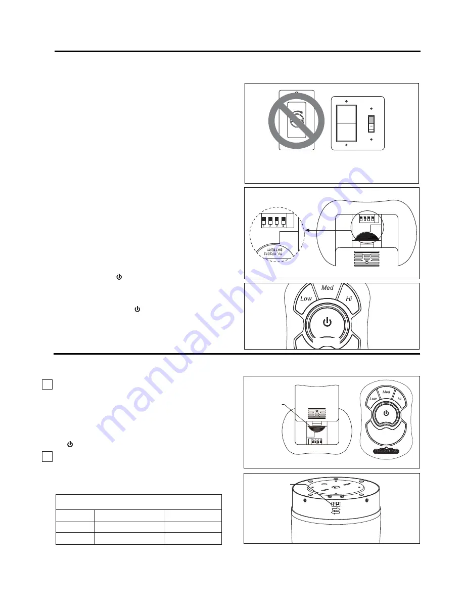
IMPORTANT:
Using a full range dimmer switch
(not included) to control fan speed will damage the fan.
To reduce the risk of fire or electrical shock, do not use
a full range dimmer switch to control the fan speed.
(Figure 1)
How to Set Up Your TR33WH Remote Control
Figure 2
Remote Transmitter
Unit Detail
1 2 3 4
ON ECE
ON ECE
NOTE: You must press the “
button ” within 60 seconds of
restoring power to the fan. Remote does not need to be
re-learned when replacing the battery. Please note, the remote
can learn multiple receivers. 60-second time limit should eliminate
need for this.
2.
3.
After installing the unit and restoring power to your fan,
press and hold the “ button” 1~5 seconds, light will flash
twice, which indicates that the learning process has
completed. (Figure 3)
Setting the Code:
The remote unit has 16 different
code combinations. To prevent possible interference from
or to other remote units such as garage door openers, car
alarm or security systems, simply change the combination
code in your transmitter and receiver. To set the code,
perform these steps.
7UDQVPLWWHU
remove battery cover by pressing firmly
below arrow and sliding battery cover off. Slide code
switches to your choice of up or down position. Factory
setting is all up. Do not use this position. With a small
screwdriver or ball point pen slide switches up or down
(Figure 2). Replace battery cover on the transmitter.
14
How to Operate Your TR33WH Remote Control
1.
Operating & Using Remote Transmitter (Figure 1):
Install 3 volt battery (If not using for long periods of time,
remove battery to prevent damage to transmitter). Store
the transmitter away from excess heat or humidity.
+,3XVK%XWWRQ±KLJKIDQVSHHG
0('3XVK%XWWRQ±PHGLXPIDQVSHHG
/2:3XVK%XWWRQ±ORZIDQVSHHG
2))3XVK%XWWRQ±IDQRII
Figure 1
If airflow is desired in the opposite direction, turn
the fan off and wait for the blades to stop turning.
Then slide the reverse switch on side of motor
assembly to the opposite position and turn fan on
again. (Figure 2)
2.
Reverse Switch Information
Season
Rotation Direction Switch Position
Summer
Counter-Clockwise
/HIW
Winter
Clockwise
Right
5(027(
3V, CR2032
%$77(5<
3&6
&21752/
ECE
Figure 2
REVERSE
6:,7&+
Figure 3


