background image

6

How to Hang and Wire Your Ceiling Fan

Mounting Motor Unit:


1.

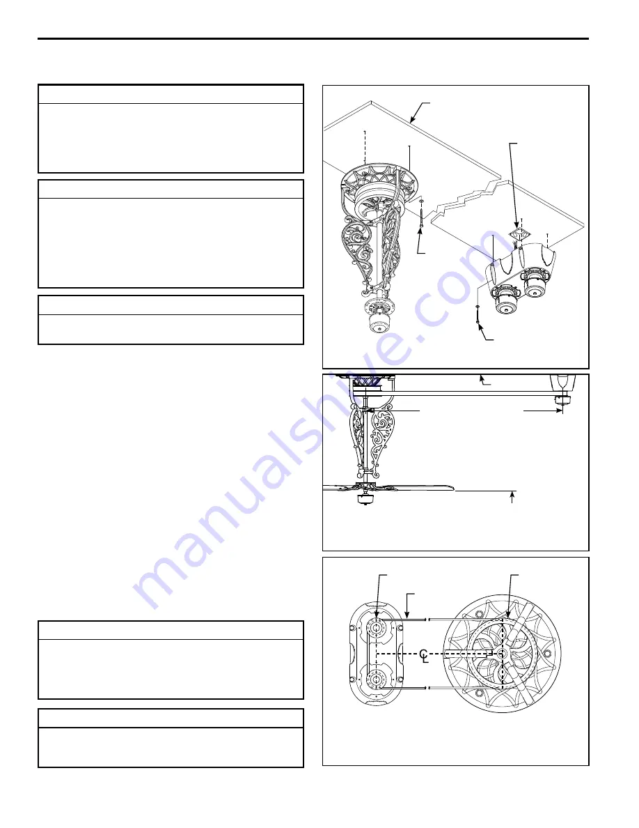
 Mark mounting hole positions for the motor unit onto 

the ceiling or supporting member.

2.

 Drill 

1

8

˝

 pilot holes into the plywood base or supporting 

member to prevent splitting or cracking.  While supporting 

the Motor Assembly, screw the lag bolts (¼

˝

 x 2

˝

approximately “half-way” in.  This will allow enough space 

between the ceiling panel and motor base to properly 

wire your motor.

3.

 Connect the green grounding lead from the fan motor 

to the supply grounding conductor (this may be a bare 
wire or wire with green colored insulation). Securely 
connect wires with wire connectors supplied. (Figure 4)

NOTE:

 Motor assembly 

must

 be perpendicular to the 

direction of belting running from the motor to the first fan.  

Drive belt 

must

 wrap around both motor pulleys.  Be sure 

to position the fan pulley so that the belt won’t rub against 

the support legs. 

(Figure 3)

  Be sure of your belt-layout 

plans before installing both the motor and fan assemblies.

Ceiling

No

less than

7 ft from 

fl

 oor

Figure 1

2

˝

 Lag Bolt

& Flat Washer

(4 places)

3

˝

 Lag Bolt

& Flat Washer

(3 places)

Outlet Box Flush

to Finished 

Ceiling

Plywood (¾

˝

 thick min.)

Backing Secured to

Structural Member

Figure 2

16 ft max - motor to head

6 ft min

(16 ft max - head to head)

Figure 3

Motor Pulley (2)

Fan Pulley

Belt

NOTE:

 Switch housing caps and flywheel assemblies 

removed for belt detail clarity

CAUTION

Do not connect fan blades until the fan is completely 

installed.  Hanging fan with blades connected may result 

in damage to the fan blades.

WARNING

Do not install or use fan if any part is damaged or 

missing.  This product is designed to use only those 

parts supplied with this product and/or any accessories 

designated specifically for use with this product by 

Fanimation.  Substitution of parts or accessories not 

designated for use with this product by Fanimation could 

result in personal injury or property damage.  Contact 

your retail store for missing or damaged parts.

INSTALLATION NOTE

HEAVY! Two or three people are required to hang the 

motor and fan / pulley assemblies.

INSTALLATION NOTE

The fan must be hung with at least 7’ of clearance 

from floor to blade.  The maximum overall distance 

between motor & pulley is 16´ and the minimum is 6´.


The maximum overall distance between two fan/pulley 

assemblies is 16´ and the minimum is 6´. 

(Figure 2)

INSTALLATION NOTE

It is recommended that each fan and the motor have ¾

˝


plywood backing secured to a structural member for 

adequate support (Figure 1).  A 120 VAC electrical feed, 

centered under the motor unit and wired to a standard 

wall switch (user supplied) is required.  The motor unit 

will not operate more than 6 fan assemblies or idlers.

Summary of Contents for Bourbon Street FP510 Series

Page 1: ...0 Fan Series Model No FP580 Motor Series The Bourbon Street Belt Driven Ceiling Fans WARNING Support Directly From Building Structure Long Neck FP520 Net Weight 48 lbs 21 7 kg Short Neck FP510 Net Wei...

Page 2: ...he extent permitted by law Some states do not allow limitations on implied warranties Fanimation will not be liable for incidental consequential or special damages arising out of or in conjunction wit...

Page 3: ...refer to exploded view illustrations Figure 1 2 3 pages 13 15 17 Check to see that you have received the following parts Motor Assembly and hardware parts Figure 1 Fan Pulley Assembly and hardware par...

Page 4: ...See Catalog or visit our website www fanimation com for more information Figure 2 FP510 Short FP520 Long Pulley Assembly and Hardware Parts Identification Belt NOTE If you are uncertain of part descri...

Page 5: ...er 4 places 2 Lag Bolt Flat Washer 4 places Outlet Box Flushed to Finished Ceiling Plywood thick min Backing Secured to Structural Member INSTALLATION NOTE It is recommended that each fan and the moto...

Page 6: ...t min 16 ft max head to head Figure 3 Motor Pulley 2 Fan Pulley Belt NOTE Switch housing caps and flywheel assemblies removed for belt detail clarity CAUTION Do not connect fan blades until the fan is...

Page 7: ...unit Figure 3 2 Using the 3 16 drill bit drill pilot holes into the plywood base or supporting member Mount the Fan Pulley Assembly on the ceiling with 3 lag bolts 5 16 x 3 and flat washers Figure 1...

Page 8: ...2 Punch two holes approximately 1 8 inch in diameter through the overlapping belts spacing them one inch apart with the punch tool supplied Figure 2 3 Using the rivets rivet washers and the rivet tool...

Page 9: ...this assembly see below See Catalog or visit our website www fanimation com for more information Figure 1 Figure 2 Blade Blade Holder Options FP1018 Reversible Oak Walnut Wood Blade sold separately Tr...

Page 10: ...are not required and should be avoided to prevent damage to finish Blade Cleaning Periodic light dusting of the Palm Leaf Woven Bamboo Wooden or Wicker blades is recommended A feather duster will wor...

Page 11: ...d off 2 FAN SOUNDS NOISY 1 Loose screws in motor housing 2 Screws securing fan blade are loose 3 Pulley set screw loose 4 Rivets on belt make clicking sound 1 Check to make sure all screws in motor ho...

Page 12: ...x 2 Black 4 14 Flat Washer Black 4 17 Wire Connectors 3 Belt Rivet Parts Bag Containing HDW580RV 15 Rivet Washers 16 16 Rivets 16 Miscellaneous Tools 18 Clamps 2 P128015 19 Rivet Tool 1 P128005 20 Pun...

Page 13: ...Bourbon Street Motor Pack FP580 NOTE The illustration shown is not to scale or its actual configuration may vary Wires partially removed for clarity 1 3 2 4 7 5 6 10 11 13 14 12 8 Figure 1 9 13 14 RE...

Page 14: ...5 16 18 x 1 19 Double Fan Pulley 1 P505 20 Bearing 1 25 Blade Holder Set Wood 5 BH1018 26 Belt 40 ft roll 1 B500 Loose Parts Bags Containing 21 Screw Lag 5 16 x 3 Black 3 HDWFP520 22 Flat Washer 5 16...

Page 15: ...tual configuration may vary Exploded View The Bourbon Street Fan Pulley Assembly Pack FP510__ Short 2 Figure 2 3 15 14 16 11 9 10 3 14 9 7 12 8 5 4 1 6 13 17 18 10 9 13 20 19 fastens under the Fan Bas...

Page 16: ...Hex Head Bolt 20 x 1 Black 6 11 Hex Head Bolt 20 x 1 Black 3 12 Fan Base 1 P502 13 Nut Hex 20 3 14 Nipple 1 8 x 2 15 Center Shaft OD x 29 1 16 Bushing Oilite 3 8 x x 1 17 Shaft 29 Black Oxide 1 18 So...

Page 17: ...le or its actual configuration may vary Exploded View The Bourbon Street Fan Pulley Assembly Pack FP520__ Long Figure 3 2 3 5 4 1 10 9 7 8 8 10 9 11 9 14 16 17 15 3 14 6 13 fastens under the Fan Base...

Page 18: ...10983 Bennett Parkway Zionsville IN 46077 888 567 2055 FAX 866 482 5215 Outside U S call 317 733 4113 Visit Our Website www fanimation com Copyright 2007 Fanimation 2007 09...

Reviews: